Cover removal/installation, Cover removal/installation -9 – JLG 15/20MSP Service Manual User Manual
Page 66
SECTION 4 - CONTROL COMPONENTS
4-10
– JLG Lift –
3121231
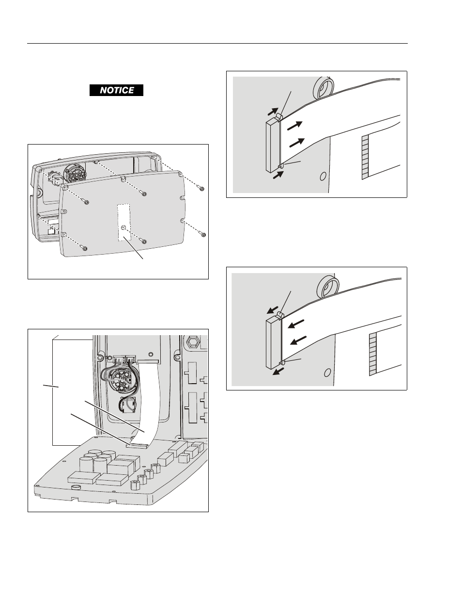
Cover Removal/Installation
THE MAIN CIRCUIT BOARD AND THE SMALLER LCD CIRCUIT
BOARD MOUNTED TO THE COVER ASSEMBLY, COMMUNICATE
THROUGH A RIBBON CABLE. REMOVE THE COVER CAREFULLY
ONCE THE COVER SCREWS ARE REMOVED FROM THE BACK OF
THE MODULE.
Cover Installation
1. Remove the (6) Hex Socket Screws from the Heat Sink/
Base. One screw is under the Warranty/Tamper Label.
Disconnect the Ribbon Cable
1. Ribbon Cable Connector
3. Support for Cover
2. Ribbon Cable
1
1
2
3
Release Ribbon Cable
1. Ribbon Cable Connector Tabs
(Push tabs away from connector to release
cable then slide cable out of connector)
Note: Connector works same at both ends of the ribbon cable.
Reconnecting Ribbon Cable
1. Ribbon Cable Connector Release Tabs
(Slide cable into connector then push tabs
back into connector)
Note: Connector same at both ends of the ribbon cable.
1
1
1
1