Code 16 - lift down valve - short circuit, Code 17 - ground control module - in fold back, Code 18 - alarm - short circuit – JLG 15/20MSP Service Manual User Manual
Page 145: Code 16 - lift down valve - short circuit -25, Code 17 - ground control module - in fold back -25, Code 18 - alarm - short circuit -25, See table 6-20, Ge 6-25, See table 6-21, See table 6-22
SECTION 6 - TROUBLESHOOTING
3121231
– JLG Lift –
6-25
Code 16 - Lift Down Valve - Short Circuit
Check For These Obvious Conditions First:
• Damaged wiring in the lift down valve wiring harness or a damaged lift down valve coil.
Code 17 - Ground Control Module - In Fold Back
Check For These Obvious Conditions First:
• Has machine been operating on a continuous grade or rough terrain for a long period of time.
Code 18 - Alarm - Short Circuit
Check For These Obvious Conditions First:
• Damaged wiring in the alarm wiring harness or a damaged alarm.
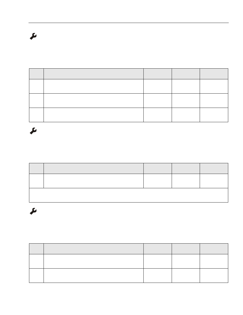
Table 6-20. Code 16 - Lift Down Valve - Short Circuit
STEP
ACTION
SPEC
YES
NO
1.
At the Ground Control Module, P1 connector, check the voltage across pins
10 and 3 to the lift down valve coil. Is reading within specification?
0 - 2V DC
Go to Step 2
Replace Ground
Control Module
2.
Remove the wire terminals at the lift down valve coil. Check resistance read-
ing of the coil. Is coil within specification?
6 Ohms
Go to Step 3
Replace Coil
3.
With the terminals still removed from the lift down valve coil, check continu-
ity of the wires from pins 10 and 3 on the P1 connector to the lift down valve.
.00 Ohms
—
Repair or Replace
Wiring
Table 6-21. Code 17 - Ground Control Module - In Fold Back
STEP
ACTION
SPEC
YES
NO
1.
Allow Ground Control Module to cool for 30 minutes. Does the machine
operate OK after cooling.
—
—
Replace Ground
Control Module
NOTE: If this is a recurring problem compare current draw of your machine with Ground Control Module specifications in
Table 6-3 - Amperage Draw for Various Components.
Table 6-22. Code 18 - Alarm - Short Circuit
STEP
ACTION
SPEC
YES
NO
1.
At the Ground Control Module, P1 connector, check the voltage across
pins-13 and 6 to the alarm. Is reading within specification?
0 - 2V DC
Go to Step 2
Replace Ground
Control Module
2.
Remove the wire terminals at the alarm, check continuity of each of the
wires from pins 13 and 6 on the P1 connector to the alarm end.
—
Replace the Alarm
Repair or
Replace Wiring