16 drive system troubleshooting, Won’t climb grade, Machine drives in opposite direction – JLG 15/20MSP Service Manual User Manual
Page 165: 16 drive system troubleshooting -45, Won’t climb grade -45, Machine drive in opposite direction -45, Drive system troubleshooting, 45 machine drives in opposite direction
SECTION 6 - TROUBLESHOOTING
3121231
– JLG Lift –
6-45
6.16 DRIVE SYSTEM TROUBLESHOOTING
Won’t Climb Grade
Overview Of Procedure
The following procedure checks the drive motor and attached components for component failure, misadjustment due to
wear.
Check For These Obvious Conditions First:
• Batteries are Fully Charged (24 Volts)
• Speed Control is Set to Maximum
• Is Grade within the Maximum Allowable Specification of 20% Grade
• Does the Travel Surface allow for Proper Drive Wheel Traction
• Is Platform Load within the Maximum Rated Capacity
Machine Drives in Opposite Direction
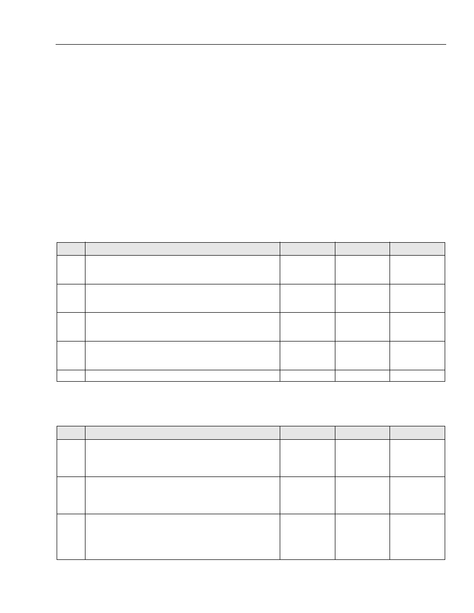
Table 6-52. Won’t Climb Grade
STEP
ACTION
SPEC
YES
NO
1.
Does machine drive straight on a level surface?
—
Go to Step 2
Refer to Machine
Won’t Drive Straight
2.
Do the left and right drive motor brakes release properly and allow the drive
wheels to rotate freely?
—
Go to Step 3
Dragging?
Repair, Replace or
Adjust Brakes
3.
Check the amperage output of the on the drive motor leads. They should not
exceed 100 amps while pulling a grade.
—
Controller will Shut
Drive Down and will
flash a 7 LED Code
Go to Step 5
4.
Check the condition of the drive motor brushes.
—
OK, go to Step 6
Worn down,
replace brushes or
drive motor
5.
If all above is OK, Drive motors are working properly. Consult Factory.
—
—
—
Table 6-53. Machine Drive in Opposite Direction
STEP
ACTION
SPEC
YES
NO
1.
At the Traction Control Module, check if the left drive motor power lead is
plugged into the M1 socket.
—
Go to Step 2
Switch the Left and
Right Drive Motor
Power Leads at the
Traction Module
2.
Remove the Right Drive Motor power lead at the Traction Control Module
(M2) and check if the WHITE wire is connected to the positive (+) terminal
and the BLACK wire is connected to the negative (–) terminal. (Reference
Figure 6-7., Electrical Diagram. (MVL/MSP)
—
Go to Step 3
Rewire as
Necessary
3.
Remove the Left Drive Motor power lead at the Traction Control Module
(M1) and check if the BLACK wire is connected to the positive (+) terminal
and the WHITE wire is connected to the negative (–) terminal. The Left
Motor Power lead is reversed from the Right Motor lead due to the reverser
harness. (Reference Figure 6-7., Electrical Diagram. (MVL/MSP)
—
Consult
Factory
Rewire as
Necessary