Gear box main disassembly, Gear box main disassembly -9 – JLG 15/20MSP Service Manual User Manual
Page 43
SECTION 3 - BASE COMPONENTS
3121231
– JLG Lift –
3-9
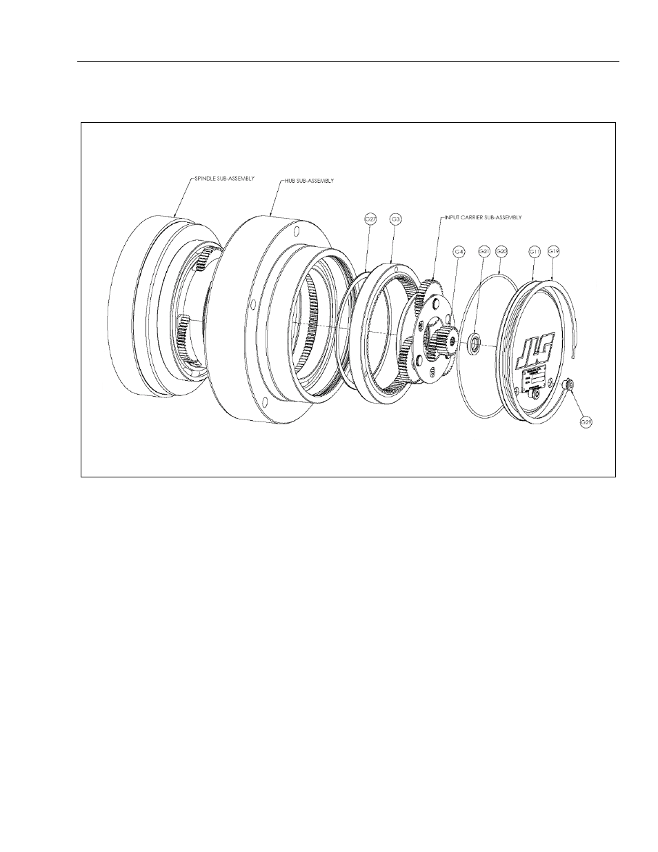
Gear Box Main Disassembly
1. Using a screwdriver, pry the end of the Retaining
Ring (G19) out of the groove in the Hub Subas-
sembly, then grasp the loose end of the Retaining
Ring and pull the rest of the way out.
2. Remove Cover (G11), Thrust Washer (G21) should
remain in the inner counter-bore of the Cover when
removed.
NOTE: To remove the cover the motor must be removed.
Slide a rod through the motor shaft hole and gently
tap with a rubber hammer to force the cover out.
3. Remove Input Sun Gear (G4).
4. Remove Input Carrier Sub-assembly.
5. Remove Cover (11) and O-ring (G20).
6. Remove Input Ring Gear (G3).
NOTE: The Input Ring Gear (G3) is held in with a press fit
on its outside diameter. Insert jacking screws (1/4-
20UNC, grade 8) with at least 1.5 inches of thread
length into each of the three tapped holes to force
the ring gear out. Be sure and alternate between the
jacking screws to keep the ring gear from becoming
misaligned in the bore. The screws will push against
the outer race of the main bearing. This bearing will
have to be replaced afterwards.
7. Using a screwdriver, remove Spiral Retaining Ring
(G27).
8. Pull Hub Sub-assembly off of the Spindle Sub-
assembly.
Gear Box Main Disassembly