JLG 15/20MSP Service Manual User Manual
Page 53
SECTION 3 - BASE COMPONENTS
3121231
– JLG Lift –
3-19
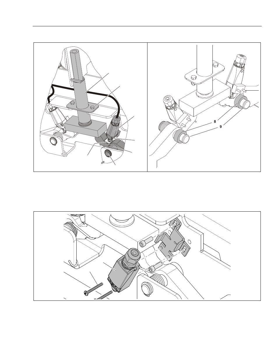
Actuator - Limit Switch - Counterweight Installation - (Machines Prior to S/N-0130013258)
(Same both sides of machine)
1. PHP Actuator
2. Actuator Attach Screw/Nut
3. Limit Switch (a)
4. Limit Switch Attach Screws (b)
5. Shim, Adhesive-Backed (max. 2 per switch) (c)
6. Left Side Torsion Spring (yellow)
7. Counterweight Attach Pin
8. Spacer
9. Pivot Pin and Retaining Ring
Pot-Hole Switch and Mounting Bracket - (Machines S/N-0130013258 to Present)
NOTE: (a) When the pothole is in the deployed position (bars down), adjust plunger just past "click", tighten screws to
frame.
(b) Apply Loctite #222 to screw threads before tightening.
(c) Add as required if switch is adjusted to maximum and plunger has not clicked to engage switch.
1
2
3
4
5
6
7
3
4