See table 6-38, Ge 6-34 – JLG 15/20MSP Service Manual User Manual
Page 154
SECTION 6 - TROUBLESHOOTING
6-34
– JLG Lift –
3121231
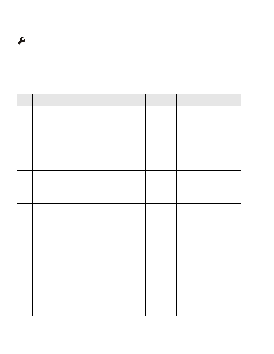
Code 40 - Obstruction Sensor System - No Communication with Ground Control Module
Check For These Obvious Conditions First:
• Is machine equipped with an Obstruction Sensor System?
• Are the electrical harness connectors from the OSS Module through the Platform Junction Box to the Ground Control
Module tight and undamaged?
Table 6-38. Code 40 - OSS - No Communication with Ground Control Module
STEP
ACTION
SPEC
YES
NO
1.
Is machine equipped with an OSS system?
—
Got to Step 4
Go to Step 2
2.
At the Ground Control Module, enter programming mode and view if OSS is
enabled. Is OSS enabled?
X = No
Go to Step 3
Replace Ground
Control Module
3.
In Service Level Programming mode, Disable Obstruction Senor System.
X=No
—
—
4.
With machine powered up, check if the RED LED is lit on the front of the OSS
Module.
—
Go to Step 5
Go to Step 10
5.
Check continuity from pin-9 on the OSS module (9-pin connector) to the
platform junction box pin-2 (4-pin connector).
—
Go To Step 6
Inspect Wiring
and Harness
Connectors
6.
Check continuity from platform junction box pin-2 (4-pin connector) to the
Ground Control Module (P-4 connector) pin-7.
—
Go to Step 7
Inspect Wiring
and Harness
Connectors
7.
Check continuity from pin-9 on OSS module (9-pin connector) to the
Ground Control Module (P-4 connector) pin-7.
—
Go to Step 8
Inspect
Connection at the
Platform Junction
Box
8.
Program the Ground Control Module to Disable the OSS System. Does fault
condition still appear?
—
Replace the Ground
Control Module
Go to Step 9
9.
Replace the Obstruction Sensor System and check for fault.
—
Replace the Ground
Control Module
—
10.
Disconnect 9-pin connector at the OSS Module. Place a positive (+) lead
on Pin-1 and a negative (–) lead on pin-5. Check for 24v DC.
24V (DC)
Replace the OSS
Module
Go to Step 11
11.
Check the wiring harness from the Platform Junction Box connector to the
Ground Control Module, positive (+) lead on pin-1 to negative (–) lead on
pin-4. Check for 24v DC.
24V (DC)
Repair or Replace,
OSS to Junction Box
Wire Harness
Go to Step 12
12.
At the Ground Control Module (P-4 connector) check voltage between pin-8
and pin-2, place positive (+) lead on pin-8.
24V (DC)
Repair or Replace,
Junction Box to
Ground Control
Module
Wire Harness
Replace Ground
Control Module