Wheel drive assembly - removal from machine, Wheel drive assembly - removal from machine -5 – JLG 15/20MSP Service Manual User Manual
Page 39
SECTION 3 - BASE COMPONENTS
3121231
– JLG Lift –
3-5
Wheel Drive Assembly - Removal From Machine
The electric wheel drive assemblies are mounted indepen-
dent of each other in the base frame at the rear of the
machine.
The wheel drive assembly consists of an 24V DC electric
motor driving a 30.68:1 ratio gear box, the assembly also
included a friction disk parking brake assembly. This
brake assembly is mounted internally on the drive assem-
bly between the drive motor and the gear box assembly.
1. Disconnect the positive battery terminal from the left
side battery.
2. Raise the rear drive wheels of the machine off the
ground, use a fork truck or floor jack. Place a block
or safety stand under machine.
3. Remove the wheel drive cover assembly.
4. Remove the drive wheel mounting lugs and remove
the drive wheel(s).
5. Disconnect the power harness terminals and brake
harness connector(s) from the drive motor.
6. Remove the six (6) hex head cap screws and wash-
ers attaching the drive assembly to the frame.
7. Carefully slide the drive motor assembly out of the
base frame for disassembly.
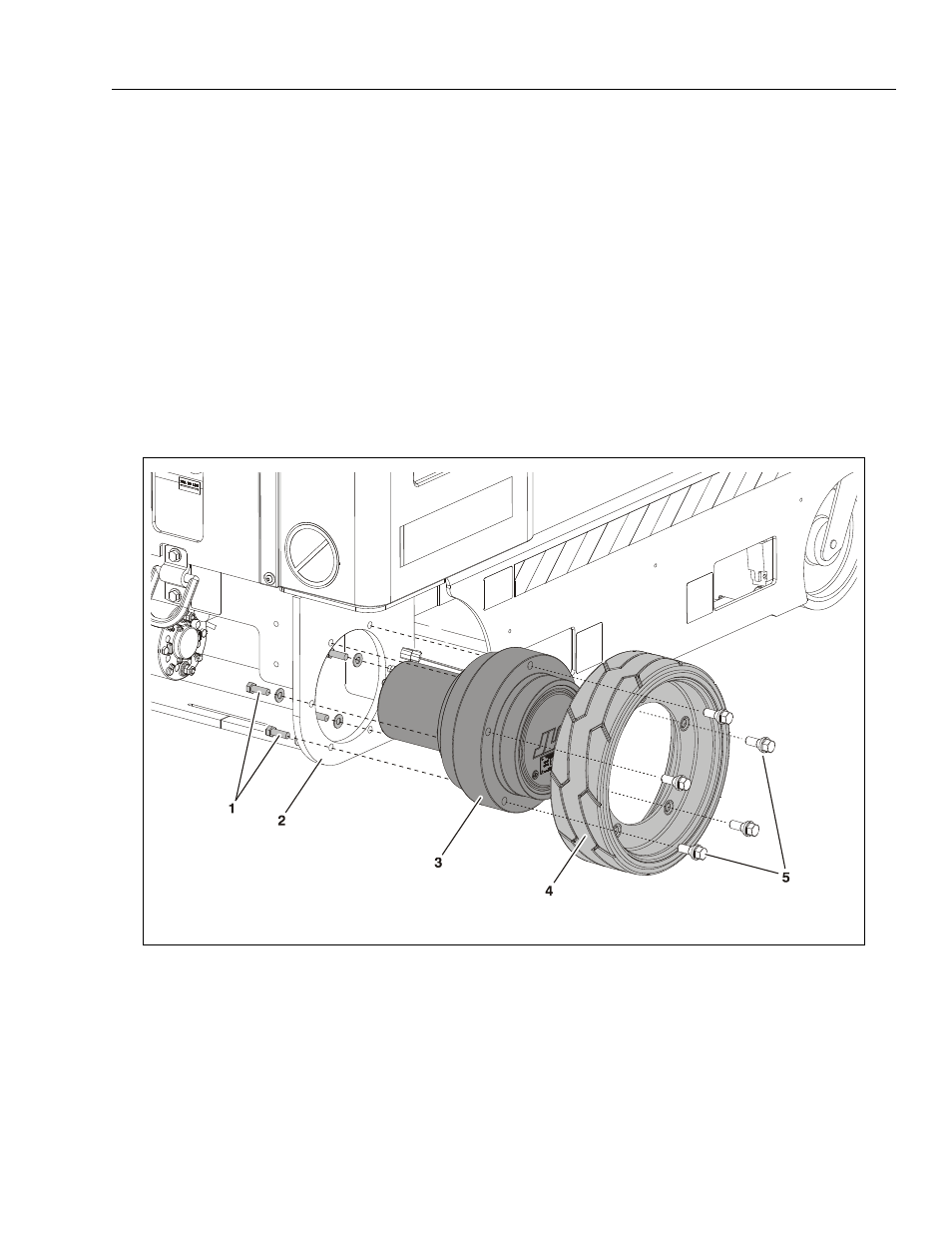
Wheel Drive Assembly - Installation (Right Side Shown)
1. Mounting Bolts/Washers (a)
2. Frame Mounting Surface
3. Wheel Drive Assembly
4. Drive Wheel
5. Wheel Mounting Lugs (b)
NOTE: Installation same for left and right drive motor - (a) Apply Loctite #242 to threads before tightening.
(b) Tighten to 120 ft. lbs. (534 N-m)