Warning – Snorkel S3010E User Manual
Page 31
Chapter 8 – Prestart Inspection
S3010E - 514226-000-ANSI
27
Horn Button
The horn is operational when the machine is set up for
operation from the upper control panel (refer to Figure
8.15).
Press the horn button to ensure that it sounds to warn
personnel in the area.
Lowering Alarm
To test the lowering alarm from the upper controls:
1. Raise the platform approximately 6′ (1.8 m).
2. Lower the platform and make sure the alarm sounds.
Drive Alarm
The machine may be equipped with a drive alarm.
Drive in both the forward and reverse directions to ensure
that the alarm sounds to warn personnel in the area that
the aerial platform is in motion.
Flashing Light
The machine may be equipped with an optional flashing
light mounted on the machine.
To inspect the flashing light:
1. At the lower controls, pull the emergency stop button
outward and turn the control selector switch to either
the lower or upper control position.
2. Operate any control function and visually check to
see that the light is flashing approximately one flash
per second.
Note
There is not an off switch for the flashing light.
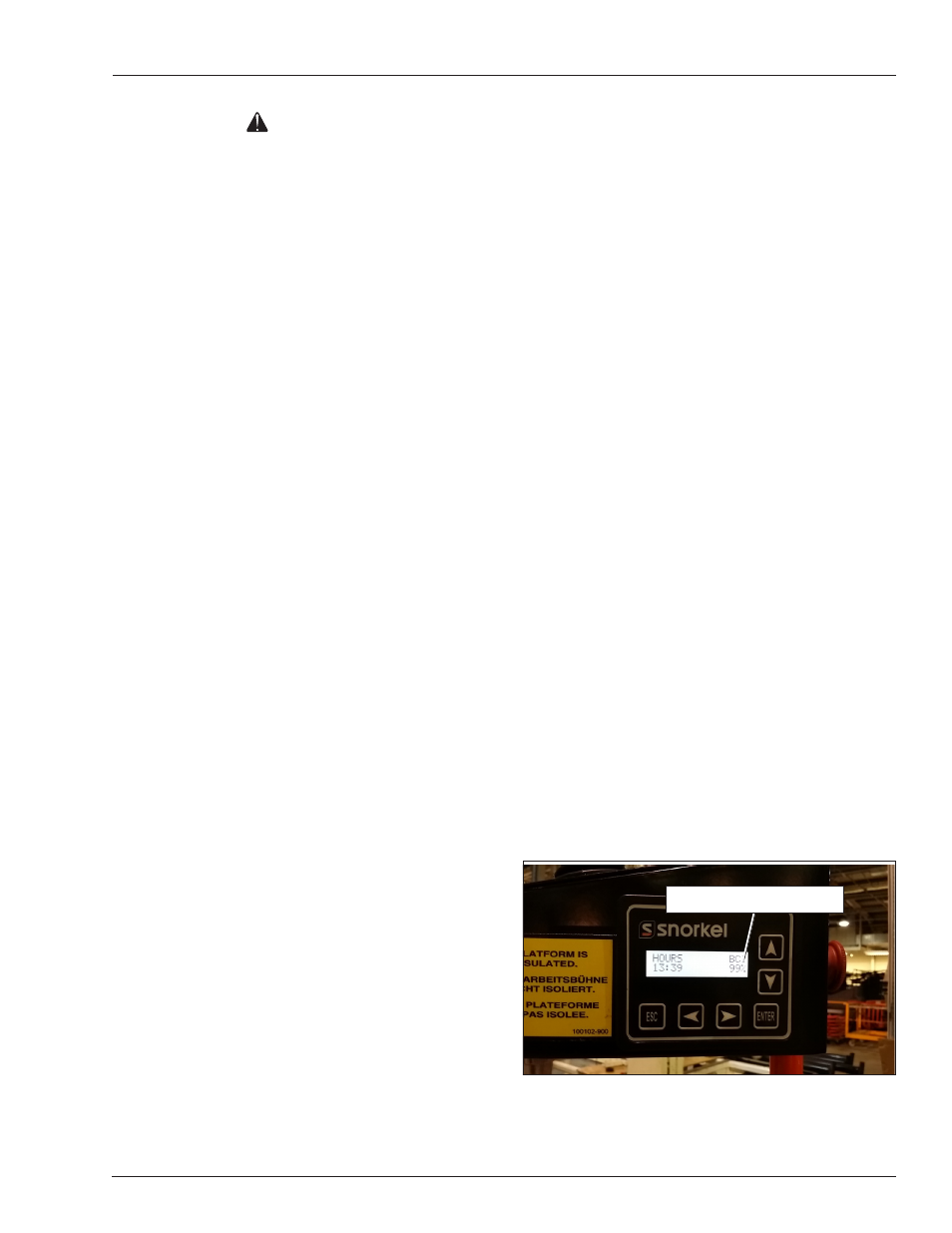
Battery Condition Indicator
The battery condition indicator (refer to Figure 8.16) is
located on the upper control panel within the Diagnostic
Center LCD.
Figure 8.16 – Upper Controls
Warning
The potential for an accident increases when operat-
ing an aerial platform that is damaged or malfunction-
ing. Death or serious injury could result from such
accidents. Do not operate the aerial platform if it is
damaged or malfunctioning.
4. Test the interlock switch by moving the joystick
without engaging the interlock switch. If movement
occurs the interlock is not functioning properly. Do not
operate the machine until the problem is corrected.
5. Place the drive/lift selector switch in the drive position
and test the operation of the joystick in all directions.
The lift functions should not operate with the selector
in the drive position.
Squeeze and hold the interlock switch against the
joystick. Test the steering in both directions using the
joystick.
y
To steer to the right, move the joystick to the right.
y
To steer to the left, move the joystick to the left.
6. Test the operation of the brakes while operating the
aerial platform from the upper controls. The brakes
are engaged when:
y
the joystick interlock is released.
y
the drive/lift selector switch is in the lift position.
y
the emergency stop button is pushed down.
Placing the drive/lift selector in the drive position, en-
gaging the interlock and moving the joystick, releases
the brakes.
7. Place the drive/lift selector switch in the lift position
and test the operation of the joystick in both direc-
tions. The drive functions should not operate with the
selector in the lift position.
Squeeze and hold the interlock switch against the
joystick. Test the joystick in both directions.
y
To raise the platform push the joystick forward.
y
To lower the platform pull the joystick backward.
Emergency Stop
To test the emergency stop button from the upper controls:
1. Push the emergency stop button inward to turn off
electrical power.
2. Verify that the upper control platform and drive func-
tions do not operate.
Battery Condition Indicator