Snorkel SL30SL-sn13772-49999 User Manual
Page 9
Seite 50
Betriebsanleitung
060588-026 SL26/30SL
Wartung
M
O T O R
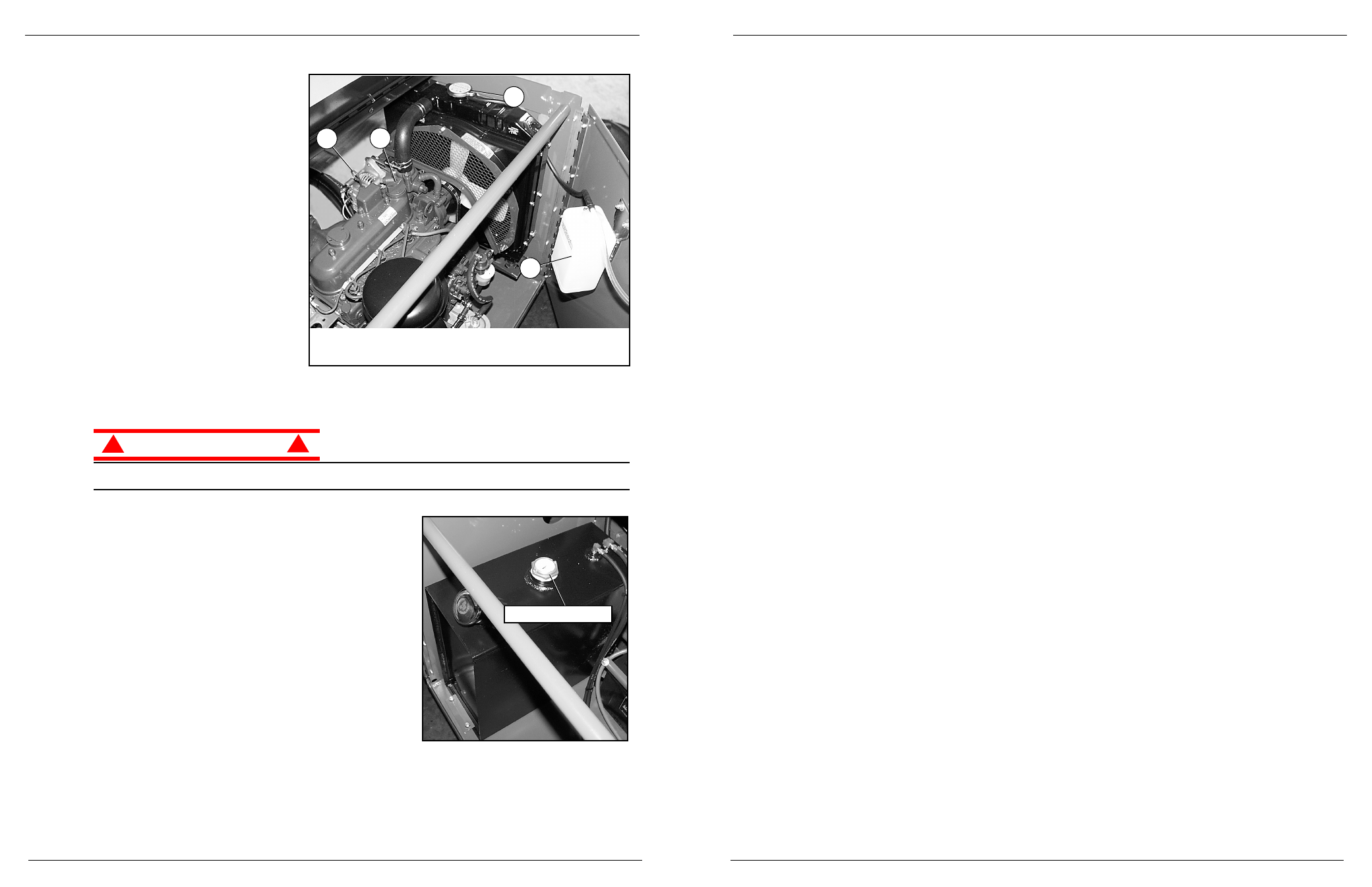
Abbildung 8:
Motor
K
ÜHLMITTEL
Der Nachfüllbehälter für das Kühlmittel
befindet sich an der Innenseite der Tür
des Aggregats.
1. Den Deckel am Nachfüllbehälter
entfernen.
2. Kühlmittel bis zur Markierung „Voll“
(FULL) auffüllen.
ANMERKUNG:
Den Kühlerkappe solange nicht
entfernen, wie der Motor noch heiß ist.
Ö
L
Der Motor
darf nicht laufen
, wenn das
Motoröl überprüft und aufgefüllt wird.
Zum Wechsel des Ölfilters siehe
Wartungshandbuch.
1. Den Ölmessstab entfernen und die
Markierungen für den Ölstand
überprüfen.
2. Bei niedrigem Ölstand die
Öleinfüllkappe entfernen.
3. Mit entsprechendem Motoröl auffüllen (siehe mitgeliefertes Handbuch für die Motorwartung).
A C H T U N G
!
!
Kühlmittel NICHT bei heißem Motor oder Kühler prüfen, da heißes Kühlmittel schwere Verbrennungen
verursachen kann.
Abbildung 9:
Kraftstoffversorgung
K
RAFTSTOFF
Der Kraftstofftank befindet sich im Aggregat. Den Kraftstoffstand
an der Kraftstoffstandanzeige an der Oberseite des
Kraftstofftanks kontrollieren.
3
4
1
2
1. Kühlerkappe
2. Nachfüllbehälter für Kühlmittel
3. Öleinfüllkappe
4. Ölmessstab
Kraftstoffstandanzeige
System Function Inspection
060588-026 SL26/30SL
Operator Manual
Page 7
1. Unhook Controller from front guardrail. Firmly grasp Controller hanger in such a manner that the Inter-
lock Lever can be depressed, while performing the following checks from the ground.
2. Pull Controller Emergency Stop Button out to ON position.
3. Turn Controller Key Switch fully clockwise to start the engine, releasing the key once the engine starts.
NOTE: On Diesel Models, if the engine is cold, depress and hold the glow plug button for 6 seconds prior to starting to
engage the glow plugs.
NOTE: If the engine does not start on the first try, the Key Switch must be returned to the OFF position before it can be
engaged to start the engine again.
4. Place Drive/Level/Lift Switch in DRIVE position.
5. With the Speed Range Switch first in HIGH TORQUE and then in HIGH SPEED, actuate the Interlock
Lever and slowly push the Control Handle to FORWARD then REVERSE positions to check for speed
and directional control. The farther you push or pull the Control Handle from center the faster the
machine will travel.
6. Push Steering Switch RIGHT then LEFT to check for steering control.
7. Place Drive/Level/Lift Switch to LEVEL. While depressing Interlock Lever actuate the Fore/Aft and
Side/Side Switches to verify they function properly. Use the Side/Side Switch and tilt the platform to one
side.
8. Rehook Controller on front guardrail.
9. Push Chassis Lift Switch to UP position and elevate platform. The platform should only elevate to the
interlock height, about 2,44 m (8 ft.) above the ground, and the Tilt Alarm should sound. If the platform
continues to elevate and/or there is no alarm STOP and remove the machine from service until repaired.
10. Lower the platform with the Chassis Lift Switch.
11. Enter the platform. Using the bubble level as a guide level the platform with the Side/Side and Fore/Aft
Switches. Dismount platform.
12. Fully elevate platform using Chassis Lift Switch.
13. Visually inspect the elevating assembly, lift cylinder, cables and hoses for damage or erratic operation.
Check for missing or loose parts.
14. Lower the platform partially by pushing Chassis Lift Switch to DOWN, and check operation of the audible
lowering alarm.
15. Open the Emergency Lowering Valve by pulling and holding the knob to check for proper operation.
Once the platform is fully lowered, release the knob.
16. Push the Chassis Emergency Stop Button.
17. With only one Emergency Stop Button pushed down, in the OFF position, operate a control to verify that
the Emergency Stop Switch is functioning. Repeat the test with only the other Emergency Stop Switch
Button OFF. If any function operates with either Emergency Stop Switch in the OFF position, STOP and
remove the machine from service until it is repaired.
18. Close and secure module covers.
19. Turn the Controller Key Switch counterclockwise to OFF.