Introduction, Pre-operation and safety inspection, System function inspection – Snorkel SB60 User Manual
Page 3
46
NOTES:
3
Introduction
This manual covers the operation of internal combustion
powered models of the SB-60 Boom. This manual must
be stored on the machine at all times.
Pre-Operation and Safety
Inspection
Carefully read, understand and follow all safety rules,
labels, and operating instructions, then perform the
following steps each day before use.
Perform a complete visual inspection of the entire unit
prior to operating. Check the following areas for
discrepancies:
1. Open panels and check hydraulic components /
hoses for damage or leaks. Check electrical
components / wiring for damage or loose connections.
2. Inspect chassis, axles, hubs, rims, and steering
linkage for damage, deformation, loose or missing
hardware, and cracked welds.
3. Check tires for damage, punctures, and inflation (if
equipped with air filled tires); tire pressure must be
5.5 bars (80 psi).
4. Check all hoses for leakage / hoses and cables for
wear.
5. Inspect elevating assembly for damage, deformation,
loose or missing hardware, and cracked welds.
6. Inspect platform and guardrails for damage,
deformation, loose or missing hardware, and cracked
welds. Insure that the sliding rail operates freely.
7. Check Hydraulic fluid level with platform fully lowered.
8. Check fluid level in batteries (see Battery
maintenance, page 9).
9. Check fuel level, add fuel if necessary (see Fueling,
page 9).
10. Check engine oil level.
11. Check air filter. Replace if necessary.
NEVER remove the cap from a hot radiator. Hot
coolant can cause severe burns
12. Ensure that radiator is cold, check coolant level. Add if
necessary. Check radiator and hoses for damage.
If you smell propane, close the supply valve on
the tank immediately until you have located and
corrected the leak.
SYSTEM FUNCTION INSPECTION
Note: Refer to figures 2 through 5 for chassis and
platform control locations.
1. Before performing the following tests, check area
around machine and overhead for obstructions, holes,
drop-offs, and debris.
2. Turn chassis key switch to chassis, and pull out
emergency stop switches at the chassis control panel
and at the platform control panel.
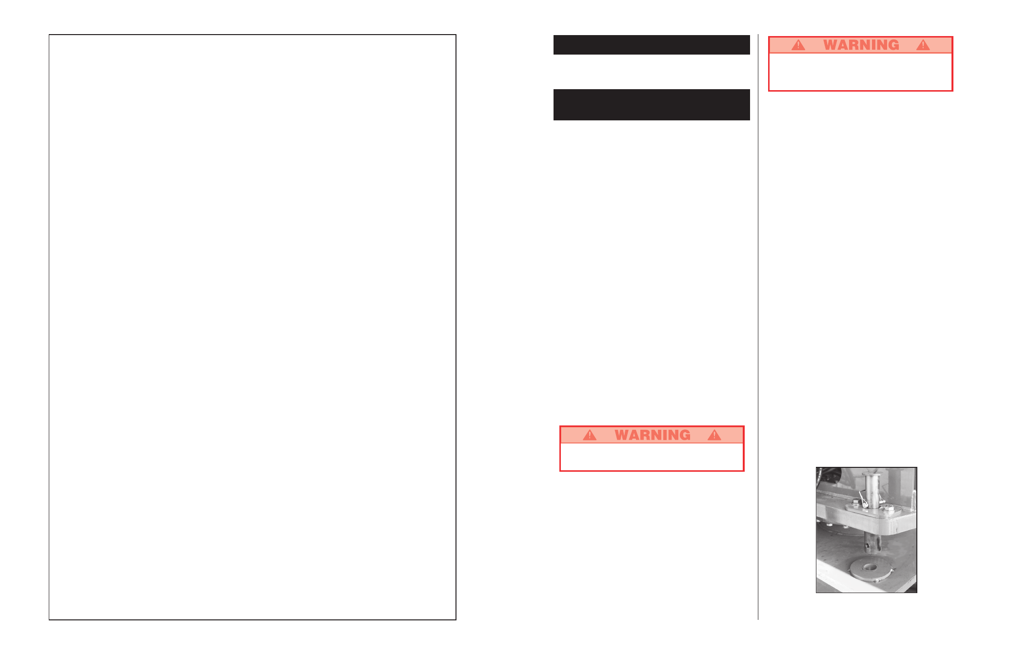
3. Retract locking bolt. See figure 1.
4. Press the engine start button to crank the engine;
release when engine starts. If engine is cold: press
the glow plug button button and hold for six seconds
prior to starting diesel models.
5. Push in the chassis emergency stop button, engine
should stop. Repeat for platform emergency stop
button. Return both emergency stop buttons to the on
position, and start engine.
6. Operate each function switch to raise / lower, extend /
retract, rotate left / right, each section of the elevating
assembly and observe the operation of the machine.
All functions should operate through full cycle
smoothly.
7. Turn chassis key switch to platform.
8. Mount the platform, attach approved fall restraint to
designated platform anchorage point. (If required by
National Legislation) Attach only one fall restraint to
each point.
9. While engaging the hand interlock, move the drive
control handle forward and reverse. Observe that
proportional functions operate smoothly, and that
brakes apply quickly after control is released.
10. While engaging the hand interlock, operate steer
switch to left and right. Observe that steering wheels
turn properly.
Figure 1: Locking bolt