Winch fitment – ARB 3462040 User Manual
Page 13
Last Rev Date: 24/7/07
Page 12 of 16
Fitting instructions# 3783176
Copyright © 2005 by ARB Corporation Limited. All rights reserved, this document must not be reproduced without the express authority of ARB Corporation Ltd
WINCH FITMENT
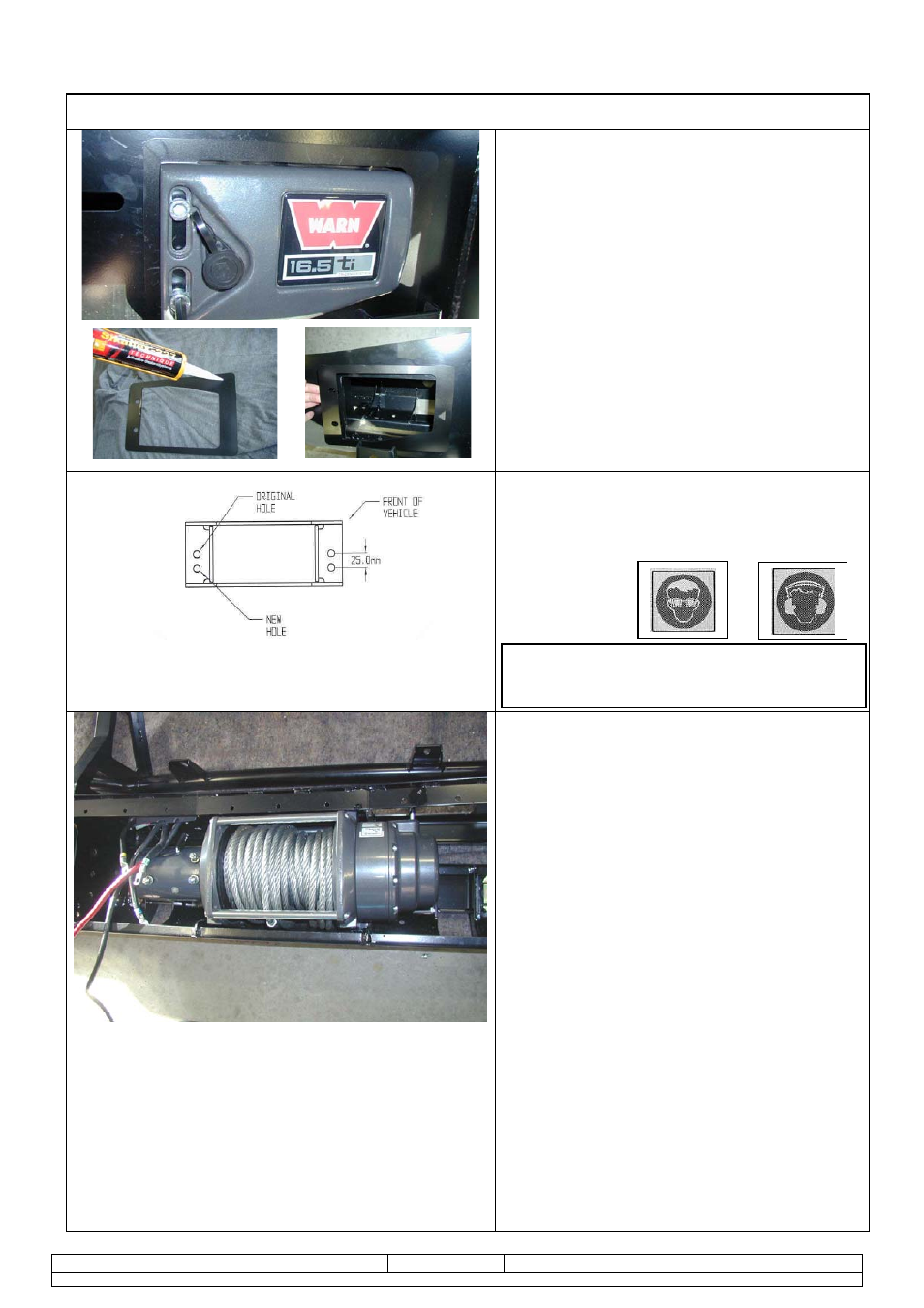
24. For 16500lb winches, apply Sikaflex (or
similar product) to rear of control box trim
plate from fitting kit (note orientation
critical to suit final position with control
box profile in pan opening).
25. Position trim plate on top of pan
centrally about control box opening and
line up with mount slots.
26. Fasten in position with 2 x M10 cap
screws and flange nuts from fitting kit.
On some models, the roller fair lead must
be drilled prior to fitment.
27. Mark out as shown and using a 13.0
mm drill bit, drill two holes as shown in
diagram.
28. Viewed from front of vehicle the winch
clutch (handle) must be positioned on the
LH side (same side as smaller square
access hole in pan). Cable must spool
from the bottom of winch. Draw off
enough cable so cable crimp can be
pulled through roller fairlead.
29. Bolt winch in position with the roller fair
lead in place.
Hint: To increase access to mount bolts in
front of roller fairlead, remove circlips from
bottom of each vertical roller shaft, push
shaft up so roller can be dislodged
sideways. Do up bolts in fairlead and
winch, then refit circlip.
30. Connect the winch control box cables
to the winch motor. Refer to the Warn
handbook for additional information.
Connect the long winch + & - cables to the
vehicle after the bar is installed.
Refer to the Warn winch manual for vehicle
wiring instructions.
Warning: Drilling operations can result in
flying metal debris, safety glasses should be
worn
.