Clearance rings, impeller measurement, 750 - 1,250 gpm pump – Hale RSD User Manual
Page 85
85
RSD Series Single-Stage PTO Pumps
p/n: 029-0020-92-0
Co rr ec tive M ain te n an ce
❑
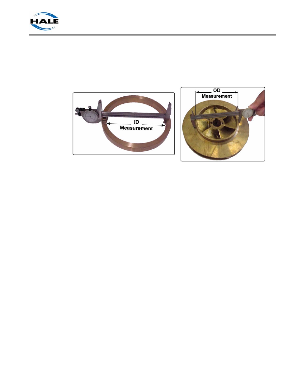
Clearance Rings, Impeller Measurement
(See Figure 6-7: “Clearance Ring and Impeller ID / OD Measurement.”)
Figure 6-7: Clearance Ring and Impeller ID / OD Measurement
Inspect the front and back of both clearance ring IDs and ODs in several
places for signs of wear. Using a caliper, measure the diameters of each
ring in several places.
Note: Clearance rings should be measured while pressed into the body.
When new, the radial clearance between the impeller hub and the clearance
rings are between 0.005” to 0.007” (0.127-0.78 mm) per side. Maximum
acceptable radial clearance on used pumps is between 0.015” to 0.020”
(0.381-0.508 mm) per side.
750 - 1,250 GPM Pump
If the gap between the impeller and the clearance ring is greater than 0.020”
(0.508 mm) you must measure the impeller hub diameter.
(See Figure 6-7: “Clearance Ring and Impeller ID / OD Measurement.”) If
the impeller diameter is greater than 6.022” (153 mm), the clearance ring
must be replaced. If the impeller diameter is less than 6.022 (153 mm) but
more than 5.987” (152 mm), the impeller hub diameter can be cut (turned
down) and “undersized” clearance rings can be ordered to compensate for
the new impeller diameter. Contact Customer Service, Hale Products at
610-825-6300.