Determining the status of a system fabric module, Figure 8, Switch fabr – Brocade Communications Systems Brocade VDX 8770-4 User Manual
Page 61
Brocade VDX 8770-4 Hardware Reference Manual
41
53-1002563-02
Determining the status of a system fabric module
4
Determining the status of a system fabric module
At least one functional switch fabric module (SFM) must be plugged into slots S1 or S2 (the “control
plane slots”). If there are no functional SFMs in either slot during bootup, bootup is halted with a
message indicating that condition.
In an operational chassis, if all SFMs in the control plane slots become faulty or are removed, then
all the line cards will be faulted with a reason code that indicates no availability of an SFM. An
external raslog message will also be displayed.
Complete the following steps to determine the status of an SFM.
1. Check the LED indicators on the SFM (refer to
). The LED patterns may temporarily
change during POST and other diagnostic tests. For information about how to interpret the LED
patterns, refer to
.
2. You can use the show sfm command or the show slots command to see whether the SFM is
enabled.
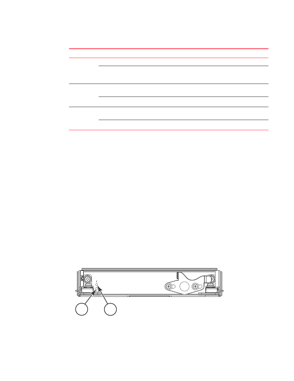
identifies the switch fabric module.
FIGURE 8
Switch fabric module
Active
Steady blue
Module is the active
MM
.
No action required.
No light (LED is off)
Module is booting up,
negotiating to be the active
MM, or is the standby MM.
No action required.
Ethernet
management
link (upper
left)
Steady green
Ethernet link speed is
10/100/1000 Mbps.
No action required.
No light (LED is off)
There is no link.
No action required.
Ethernet
management
link activity
(upper right)
Blinking green
Ethernet link is healthy and
traffic is flowing through port.
No action required.
No light (LED is off)
No traffic is flowing.
No action required.
TABLE 10
Management module LED descriptions (Continued)
LED purpose
Color
Status
Recommended action
1
Power LED
2
Status LED
2
1