Port numbering, Providing power to the brocade vdx 8770-4, Figure 3 – Brocade Communications Systems Brocade VDX 8770-4 User Manual
Page 37: Figure 4
Brocade VDX 8770-4 Hardware Reference Manual
17
53-1002563-02
Port numbering
2
8. Ensure that the switch is oriented so that the left side and port side (front) have access to
intake air.
9. Gently slide the switch onto the final installation surface, ensuring that it remains supported
during the transfer.
10. Before you apply power to the switch, you can install the MM, SFM, and line card modules as
well as power supplies to speed up your installation.
Port numbering
The Brocade VDX 8770-4 uses the following port numbering method:
•
12x40G line card module — Ports are numbered from 1 through 12 from left to right when
installed in the switch. Refer to
.
FIGURE 3
12x40G line card
•
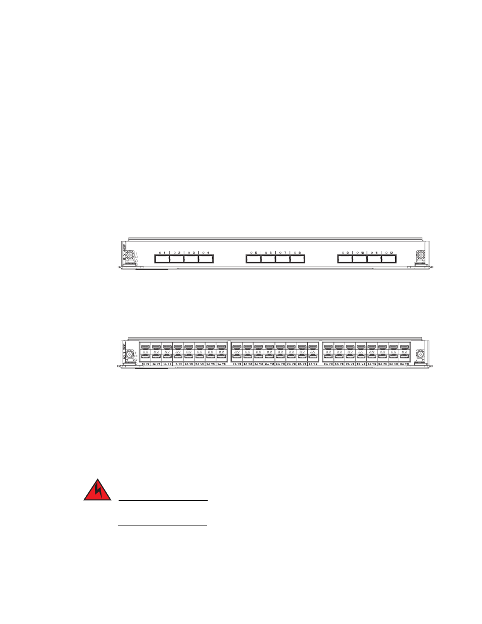
48x1G and 48x10G line card modules — Ports are numbered from 1 through 48, from left to
right, with the odd-numbered ports on the upper row and the even-numbered ports on the
lower row when installed in the switch. Refer to
.
FIGURE 4
48x10G line card (48x1G line card similar)
Providing power to the Brocade VDX 8770-4
Complete the following steps to provide power to the chassis. Each power supply has one power
cord.
DANGER
Use the supplied power cords. Ensure the facility power receptacle is the correct type, supplies
the required voltage, and is properly grounded. (D004)