Bryant 551C User Manual
Page 4
4
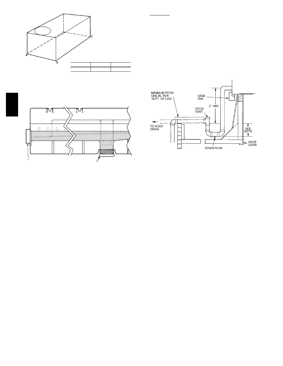
MAXIMUM ALLOWABLE
DIFFERENCE (in.)
A-B
B-C
A-C
0.5
1.0
1.0
C06110
Fig. 3
--- Unit Leveling Tolerances
DRAIN PLUG
CONDENSATE PAN (SIDE VIEW)
HORIZONTAL
DRAIN OUTLET
NOTE: Drain plug is shown in factory-installed position.
C06003
Fig. 4
--- Condensate Drain Connection
Positioning
Maintain clearance around and above unit to provide minimum
distance from combustible materials, proper airflow, and service
access. (See Fig. 7, 8 and 9.)
Position unit on roof curb so that the following clearances are
maintained:
1
/
4--
in. clearance between the roof curb and the base
rail inside the front and rear, 0.0 in. clearance between the roof
curb and the base rail inside on the duct end of the unit. This will
result in the distance between the roof curb and the base rail
inside on the condenser end of the unit being approximately
equal to Fig. 2, section C-C.
Do not install unit in an indoor location. Do not locate unit air
inlets near exhaust vents or other sources of contaminated air.
NOTE: Trap should be deep enough to offset maximum unit static
difference. A 4-in. trap is recommended.
C06004
Fig. 5
--- Condensate Drain Piping Details
Although unit is weatherproof, guard against water from higher
level runoff and overhangs.
After unit is in position, remove polyethylene shipping wrapper
and top crating.
551B
,C