T oa ) + (tr, Ra ) t (t, 100 ) + (tr – Bryant 551C User Manual
Page 30: 100 ) =t, 551b ,c
30
A proportional anticipatory strategy should be taken with the
following conditions: a zone with a large area, varied occupancy,
and equipment that cannot exceed the required ventilation rate at
design conditions. Exceeding the required ventilation rate means
the equipment can condition air at a maximum ventilation rate
that is greater than the required ventilation rate for maximum
occupancy. A proportional-anticipatory strategy will cause the
fresh air supplied to increase as the room CO
2
level increases
even though the CO
2
set point has not been reached. By the time
the CO
2
level reaches the set point, the damper will be at
maximum ventilation and should maintain the set point.
In order to have the CO
2
sensor control the economizer damper in
this manner, first determine the damper voltage output for
minimum or base ventilation. Base ventilation is the ventilation
required to remove contaminants during unoccupied periods. The
following equation may be used to determine the percent of
outside-air entering the building for a given damper position. For
best results there should be at least a 10 degree difference in
outside and return-air temperatures.
(T
OA
) + (TR
x
RA
) T
(T
O x
100 )
+ (TR
x
100 ) =T
M
T
O
= Outdoor-Air Temperature
OA = Percent of Outdoor Air
T
R
= Return-Air Temperature
RA = Percent of Return Air
T
M
= Mixed-Air Temperature
Once base ventilation has been determined, set the minimum
damper position potentiometer to the correct position.
The same equation can be used to determine the occupied or
maximum ventilation rate to the building. For example, an output
of 3.6 volts to the actuator provides a base ventilation rate of 5%
and an output of 6.7 volts provides the maximum ventilation rate
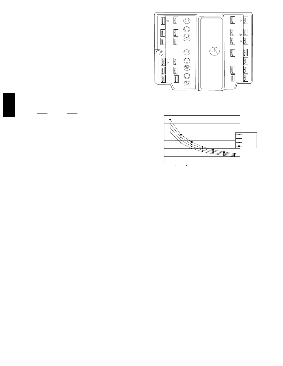
of 20% (or base plus 15 cfm per person). Use Fig. 38 to
determine the maximum setting of the CO
2
sensor. For example,
a 1100 ppm set point relates to a 15 cfm per person design. Use
the 1100 ppm curve on Fig. 38 to find the point when the CO
2
sensor output will be 6.7 volts. Line up the point on the graph
with the left side of the chart to determine that the range
configuration for the CO
2
sensor should be 1800 ppm. The
EconoMi$er IV controller will output the 6.7 volts from the CO
2
sensor to the actuator when the CO
2
concentration in the space is
at 1100 ppm. The DCV set point may be left at 2 volts since the
CO
2
sensor voltage will be ignored by the EconoMi$er IV
controller until it rises above the 3.6 volt setting of the minimum
position potentiometer.
Once the fully occupied damper position has been determined, set
the maximum damper demand control ventilation potentiometer
to this position. Do not set to the maximum position as this can
result in over-ventilation to the space and potential high-humidity
levels.
CO
2
Sensor Configuration
The CO
2
sensor has preset standard voltage settings that can be
selected anytime after the sensor is powered up. (See Table 7.)
TR1
24 Vac
COM
TR
24
Vac
HOT
1
2
3
4
5
EF
EF1
+
_
P1
T1
P
T
N
EXH
2V
10V
EXH
Set
Set
2V
10V
2V
10V
DCV
DCV
Free
Cool
B
C
A
D
SO+
SR+
SR
SO
AQ1
AQ
DCV
Min
Pos
Open
Max
N1
C06038
Fig. 37
--- EconoMi$er IV Control
0
1000
2000
3000
4000
5000
6000
2
3
4
5
6
7
8
800 ppm
900 ppm
1000 ppm
1100 ppm
RANGE
CONFIGURA
TION
(ppm)
DAMPER VOLTAGE FOR MAX VENTILATION RATE
CO SENSOR MAX RANGE SETTING
2
C06039
Fig. 38
--- CO
2
Sensor Maximum Range Setting
Use setting 1 or 2 for Bryant equipment. (See Table 7.)
1. Press Clear and Mode buttons. Hold at least 5 seconds
until the sensor enters the Edit mode.
2. Press Mode twice. The STDSET Menu will appear.
3. Use the Up/Down button to select the preset number. (See
Table 7.)
4. Press Enter to lock in the selection.
5. Press Mode to exit and resume normal operation.
The custom settings of the CO
2
sensor can be changed anytime
after the sensor is energized. Follow the steps below to change the
non-standard settings:
1. Press Clear and Mode buttons. Hold at least 5 seconds
until the sensor enters the Edit mode.
2. Press Mode twice. The STDSET Menu will appear.
3. Use the Up/Down button to toggle to the NONSTD menu
and press Enter.
4. Use the Up/Down button to toggle through each of the
nine variables, starting with Altitude, until the desired
setting is reached.
5. Press Mode to move through the variables.
6. Press Enter to lock in the selection, then press Mode to
continue to the next variable.
551B
,C