551b ,c – Bryant 551C User Manual
Page 27
27
Outdoor Enthalpy Changeover
For enthalpy control, accessory enthalpy sensor (part number
HH57AC078) is required. Replace the standard outdoor dry bulb
temperature sensor with the accessory enthalpy sensor in the same
mounting location. (See Fig. 21.) When the outdoor air enthalpy
rises above the outdoor enthalpy changeover set point, the
outdoor-air damper moves to its minimum position. The outdoor
enthalpy changeover set point is set with the outdoor enthalpy set
point potentiometer on the EconoMi$er IV controller. The set
points are A, B, C, and D. (See Fig. 36.) The factory-installed
620-ohm jumper must be in place across terminals SR and SR+
on the EconoMi$er IV controller. (See Fig. 21 and 37.)
Differential Enthalphy Control
For differential enthalpy control, the EconoMi$er IV controller
uses
two
enthalpy
sensors
(HH57AC078
and
CRENTDIF004A00), one in the outside air and one in the return
air duct. The EconoMi$er IV controller compares the outdoor air
enthalpy to the return air enthalpy to determine EconoMi$er IV
use. The controller selects the lower enthalpy air (return or
outdoor) for cooling. For example, when the outdoor air has a
lower enthalpy than the return air, the EconoMi$er IV opens to
bring in outdoor air for free cooling.
0
500
1000
1500
2000
2500
0.05
0.15
0.25
STATIC PRESSURE (in. wg)
FLOW
IN
CUBIC
FEET
PER
MINUTE
(cfm)
C06030
Fig. 28
--- Barometric Flow Capacity
0
5
10
15
20
25
30
0.13 0.20 0.22 0.25 0.30 0.35 0.40 0.45 0.50
STATIC PRESSURE (in. wg)
FLOW
IN
CUBIC
FEET
PER
MINUTE
(cfm)
C06031
Fig. 29
--- Outdoor--Air Damper Leakage
0
1000
2000
3000
4000
5000
6000
0.05
0.10
0.15
0.20
0.25
0.30
0.35
STATIC PRESSURE (in. wg)
FLOW
IN
CUBIC
FEET
PER
MINUTE
(cfm)
C06032
Fig. 30
--- Return--Air Pressure Drop
+
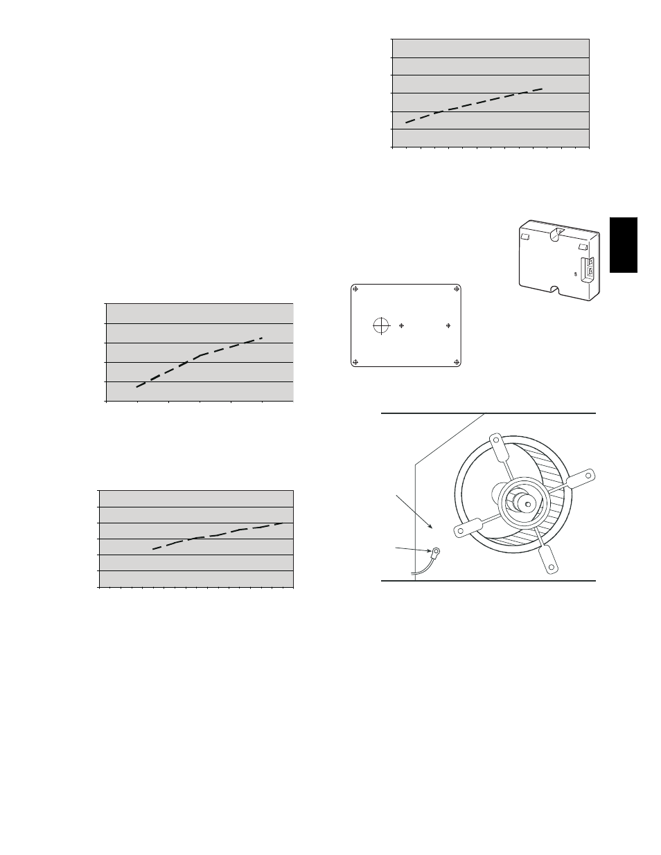
C7400A1004
HH57AC078 ENTHALPY
SENSOR
MOUNTING PLATE
C06361
Fig. 31
--- Enthalpy Sensor and Mounting Plate
SUPPLY AIR
TEMPERATURE
SENSOR
MOUNTING
LOCATION
SUPPLY AIR
TEMPERATURE
SENSOR
C06033
Fig. 32
--- Supply Air Sensor Location
551B
,C