551b ,c – Bryant 551C User Manual
Page 26
26
EconoMi$er IV Control Modes
Determine the EconoMi$er IV control mode before set up of the
control. Some modes of operation may require different
sensors. (See Table 6.) The EconoMi$er IV is supplied from the
factory with a supply--air temperature sensor and an outdoor-- air
temperature sensor. This allows for operation of the EconoMi$er
IV with outdoor air dry bulb changeover control. Additional
accessories can be added to allow for different types of
changeover control and operation of the EconoMi$er IV and unit.
Table 6—EconoMi$er IV Sensor Usage
APPLICATION
ECONOMI$ER IV WITH OUTDOOR AIR
DRY BULB SENSOR
APPLICATION
Accessories Required
Outdoor Air
Dry Bulb
None. The outdoor air dry bulb sensor
is factory installed.
Differential
Dry Bulb
CRTEMPSN002A00*
Single Enthalpy
HH57AC078
Differential
Enthalpy
HH57AC078
and
CRENTDIF004A00*
CO
2
for DCV
Control using a
Wall-Mounted
CO
2
Sensor
33ZCSENCO2
CO
2
for DCV
Control using a
Duct-Mounted
CO
2
Sensor
33ZCSENCO2†
and
33ZCASPCO2**
O
R
CRCBDIOX005A00††
*CRENTDIF004A00 and CRTEMPSN002A00 accessories are used on many
different base units. As such, these kits may contain parts that will not be
needed for installation.
† 33ZCSENCO2 is an accessory CO
2
sensor.
** 33ZCASPCO2 is an accessory aspirator box required for duct-mounted
applications.
†† CRCBDIOX005A00 is an accessory that contains both 33ZCSENCO2
and 33ZCASPCO2 accessories.
Outdoor Dry Bulb Changeover
The standard controller is shipped from the factory configured for
outdoor dry bulb changeover control. The outdoor--air and
supply--air temperature sensors are included as standard. For this
control mode, the outdoor temperature is compared to an
adjustable set point selected on the control. If the outdoor-air
temperature is above the set point, the EconoMi$er IV will adjust
the outdoor-air dampers to minimum position. If the outdoor air
temperature is below the set point, the position of the outdoor air
dampers will be controlled to provide free cooling using outdoor
air. When in this mode, the LED next to the free cooling set point
potentiometer will be on. The changeover temperature set point is
controlled by the free cooling set point potentiometer located on
the control. (See Fig. 33.) The scale on the potentiometer is A, B,
C, and D. See Fig. 34 for the corresponding temperature
changeover values.
Differential Dry Bulb Control
For differential dry bulb control the standard outdoor dry bulb
sensor is used in conjunction with an additional accessory dry
bulb sensor (part number CRTEMPSN002A00). The accessory
sensor must be mounted in the return airstream. (See Fig. 35.)
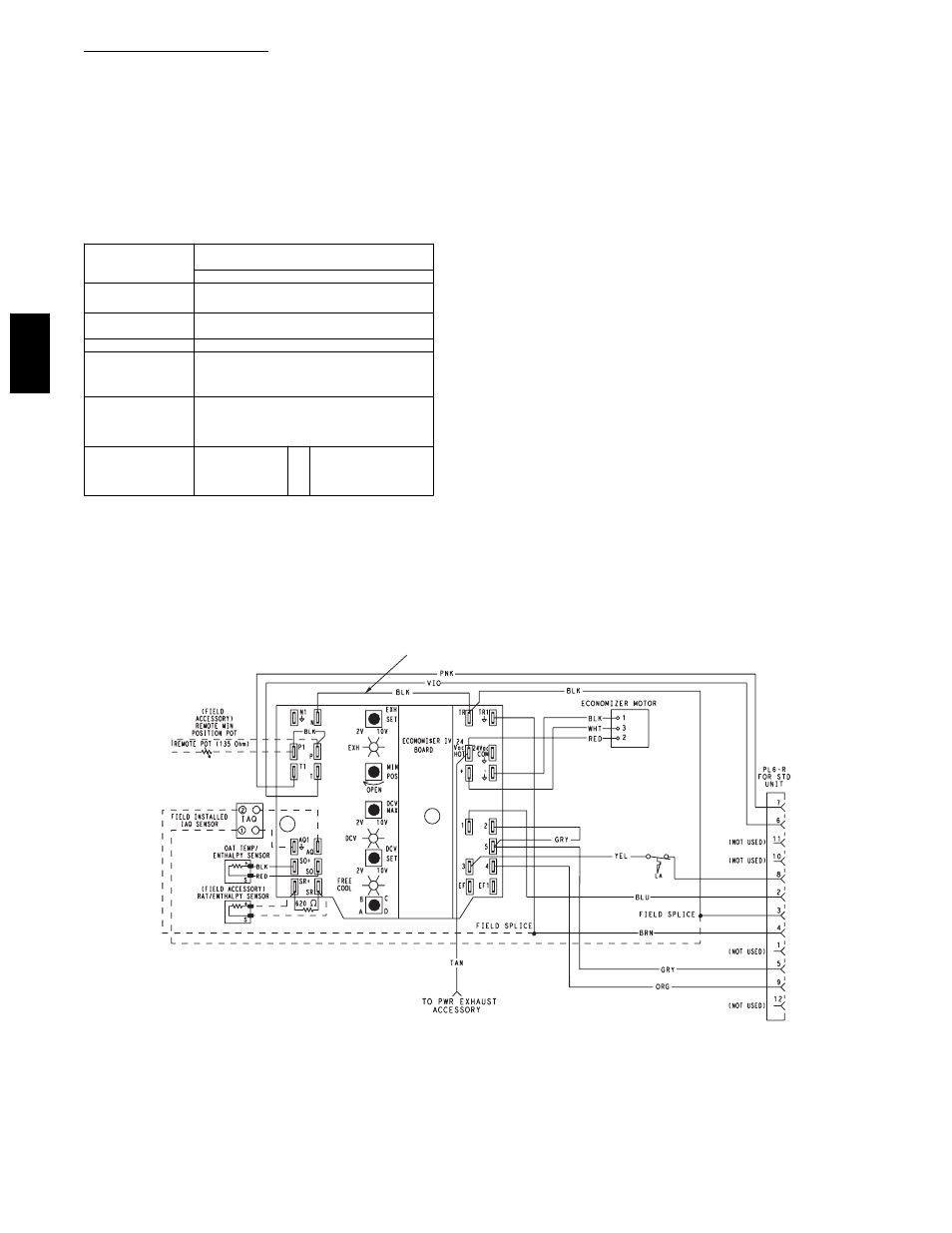
Wiring is provided in the EconoMi$er IV wiring harness. (See
Fig. 27.)
In this mode of operation, the outdoor-air temperature is
compared to the return-air temperature and the lower temperature
airstream is used for cooling. When using this mode of
changeover control, turn the enthalpy setpoint potentiometer fully
clockwise to the D setting. (See Fig. 33.)
FOR OCCUPANCY CONTROL
REPLACE JUMPER WITH
FIELD-SUPPLIED TIME CLOCK
LEGEND
DCV— Demand Controlled Ventilation
IAQ — Indoor Air Quality
LA — Low Ambient Lockout Device
OAT — Outdoor-Air Temperature
POT — Potentiometer
RAT — Return-Air Temperature
Potentiometer Defaults Settings:
Power Exhaust Middle
Minimum Pos.
Fully Closed
DCV Max.
Middle
DCV Set
Middle
Enthalpy
C Setting
NOTES:
1. 620 ohm, 1 watt 5% resistor should be removed only when using differential
enthalpy or dry bulb.
2. If a separate field-supplied 24 v transformer is used for the IAQ sensor power
supply, it cannot have the secondary of the transformer grounded.
3. For field-installed remote minimum position POT, remove black wire jumper
between P and P1 and set control minimum position POT to the minimum
position.
8
7
C06028
Fig. 27
--- EconoMi$er IV Wiring
551B
,C