0 maintenance 6.1 fyrite, Insight disassembly – Bacharach Fyrite INSIGHT User Manual
Page 25
Instruction 24-9460
44
Fyrite
®
INSIGHT
Instruction 24-9460
45
Fyrite
®
INSIGHT
If the sensor’s output is too low to be usable, then the message
“Bad Calibration Sensor End of Life, Entry Not Saved” will
appear. The sensor will now be marked as being BAD in the
DIAGNOSTICS screen.
6. Power OFF the regulator of calibration fixture and remove the CO
cylinder.
6.0 Maintenance
6.1 Fyrite
®
INSIGHT Disassembly
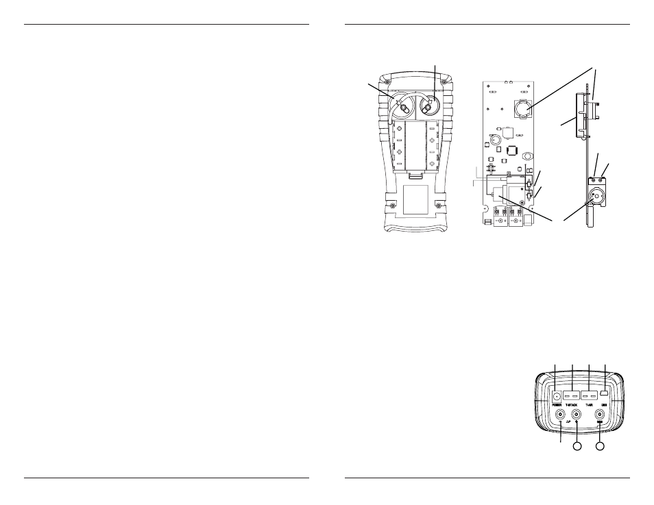
The following section describes how to disassemble the Fyrite INSIGHT to
perform necessary periodic maintenance. (See Figure 6.1 for diagram.)
Tools Required:
• Medium Phillips screwdriver
Procedure:
1. Unplug all thermocouples from bottom of analyzer.
2. Remove battery cover and then remove batteries.
3. Remove sensor caps, disconnect tubing, and then unplug all sensors.
4. Lay analyzer face down on a padded work surface; and then using
a medium Phillips screwdriver, remove the unit’s four rear-case
screws.
5. Lift rear case from analyzer and set aside.
6. Unplug electrical connector J11 from printed circuit board.
7. Lift printed circuit board from analyzer.
1. O2 Sensor
4. Sample Pump
2. CO Sensor
5. LCD Screen
3. CO Sensor Base
Fyrite
®
Insight End Plate Connectors
6. AC Power Adapter Jack (Power)
7. Sample Gas Thermocouple Connector
(T-Stack)
8. Primary Air Thermocouple (T-Air)
9. USB Connector
10. Differential Pressure Hose
(Optional)
11. Draft Hose
12. Sample Gas Hose
Fyrite
®
Insight Components
1
2
3
4
5
Side View
Front View
To O
2
To gas
J9
(Pump)
J11
(Battery)
To gas
fi tting
To O
2
sensor
cap
Fig. 6.1
6 7
9
0
8
12
11
Back
Front
Fig. 6.2