5 t-stack calibration – Bacharach Fyrite INSIGHT User Manual
Page 22
Instruction 24-9460
38
Fyrite
®
INSIGHT
Instruction 24-9460
39
Fyrite
®
INSIGHT
Procedure:
NOTE: The unit-of-measure for pressure is selected per Section 3.5.3. In
the following procedure inwc is selected, but note that any unit-
of-measure can be used for calibration purposes.
4
3
2
1
0
-1
-2
-3
-4
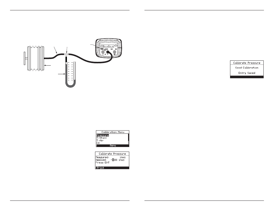
Parts:
1. 3/16" I.D. Tubing
2. Tee
3. Barbed Hose Connector
4. Bellows
5. Manometer
1
2
3
4
5
Figure 5-1 Pressure Sensor Calibration Equipment
1. Assemble the pressure sensor calibration equipment as shown in
Figure 5.1, but DO NOT connect the analyzer to the calibration
equipment at this time.
2. If not already done, power ON the analyzer and display the CALI-
BRATION LIST per Section 5.2.
3. Use the ▲▼ buttons to select PRESSURE
and then press ENTER to display the CALI-
BRATE PRESSURE screen.
"Measured" is the pressure value currently
being detected by the pressure sensor, while
"Applied is a known value of pressure that
will be applied for calibration purposes.
4. With both the -ΔP and +ΔP ports open to the atmosphere, observe
that the current Measured pressure reading should be 0.00 ± 0.01
inwc. If necessary, zero the pressure sensor per Section 4.6 then
repeat steps 2 through 4.
5. Connect the hose from the manometer to the +ΔP port and apply a
negative pressure to this port by adjusting the bellows for a manom-
eter reading of -4.00.
6. Use the ▲▼ buttons to enter an Applied value that exactly equals
the manometer reading.
The calibration range is from -6 to -2 inwc (-15 to -5 mb). An attempt
to calibrate outside this range will cause the message "Applied Value
High" (or Low) to appear at the bottom of the screen.
7. Wait until the Measured reading stabilizes,
and then press ENTER to calibrate the pres-
sure sensor's Measured value to that of the
Applied value. The message, "Good Calibra-
tion" should briefly appear, followed by the
CALIBRATION LIST screen.
8. Remove calibration equipment.
5.5 T-Stack Calibration
This procedure first zeroes and then spans the stack-temperature channel
to known temperature values.
The use of an electronic thermocouple simulator is the preferred method
of producing the desired calibration temperatures. Alternatively, ice and
boiling water baths can be used.
Materials Required:
Thermocouple simulator (K-type)
- Range: 0 to 600 °F
- Accuracy: ± 0.5 °F
(Alternatively) ice-water, boiling water, thermometer
TS-Zero Procedure:
1. Set the thermocouple simulator to room temperature and plug its
output into the T-STACK connector located at the bottom of the
analyzer.
Alternatively:
Plug the probe's thermocouple into the T-STACK con-
nector located at the bottom of the analyzer. DO NOT attach the
probe's gas hose to the analyzer's GAS port; otherwise water
will be drawn into the analyzer!
•
•
-4.02