0 operation 4.1 operating tips, 2 analyzer power on & warm up, 3 fuel selection – Bacharach Fyrite INSIGHT User Manual
Page 13
Instruction 24-9460
20
Fyrite
®
INSIGHT
Instruction 24-9460
21
Fyrite
®
INSIGHT
4.0 OPERATION
4.1 Operating Tips
When an analyzer is brought in from a cold vehicle, let it warm up
slowly to minimize condensation. Temperatures below freezing will
not damage the analyzer; however, bringing a cold analyzer into a
warm, humid environment may cause condensate to form inside the
case.
Caution
: Although the analyzer itself is not damaged by an ex-
tremely cold environment, the electrochemical sensors may be
damaged. The O
2
sensor's electrolyte will freeze at approximately
-20 °F and the CO sensor's at approximately -90 °F. If the analyzer
is exposed to an extremely cold condition, it is strongly suggested
that the sensor housings be examined for hairline cracks. Be aware
that a leaking sensor can cause chemical burns to the skin and
possibly damage the PCB assemblies.
Ensure that the analyzer is sampling fresh air when turned ON. Pulling
a stack-gas sample through the analyzer during its warm-up period will
not damage the analyzer, but it will result in incorrect sensor readings,
and may result in sensor error messages appearing after the warm-up
cycle completes.
Note that flue-gas condensate is acidic and very corrosive. It is important
not to allow the analyzer's internal components to come in contact with
condensate for long periods of time.
Before each use, inspect the filter element of the water-trap / filter as-
sembly. Replace the filter if it looks dirty.
When sampling flue-gas, keep the analyzer above the water-trap, and keep
the trap in a vertical position. This will maximize the effectiveness of the
trap and keep liquid from being drawn directly into the analyzer.
When liquid condensate is seen inside the water trap, empty the trap
before it becomes full.
When storing the analyzer, it's a good idea to empty the water trap and
leave it open to further dry it out.
Calibrate the analyzer every 6 months - 1 year to assure its accuracy.
•
•
•
•
•
•
•
•
4.2 Analyzer Power On & Warm Up
1. Connect the probe and make sure that the analyzer is properly set
up per Sec tion 3.
IMPORTANT!
DO NOT insert probe into stack before powering ON
the analyzer.
2. Place the probe in an area that contains fresh air. This ensures
that the sensors will be properly zeroed during the warm-up cycle.
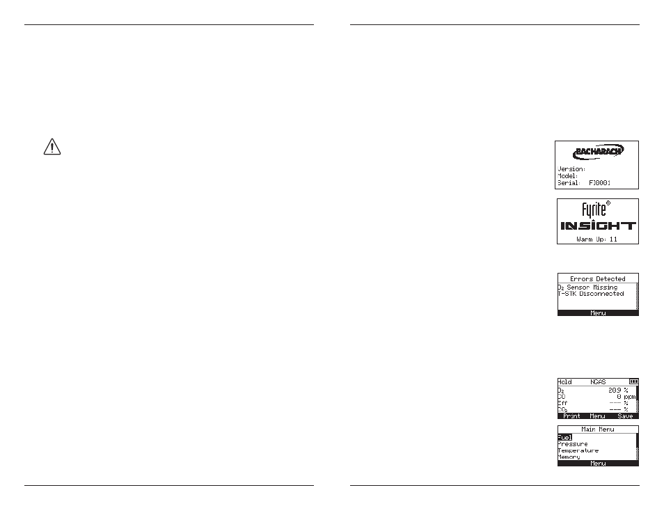
3. Power ON the analyzer by pressing the
PWR
button for at least 1 second, or until
a single beep is heard. Observe that the
analyzer's firmware version, model and se-
rial numbers are briefly displayed followed
by the Warm Up screen.
4. Wait for the analyzer to count down its 60
second warm-up period; after which, the in-
strument will display the Combustion Test
HOLD screen.
If, however, any errors were detected during
warm-up, the message "ERRORS DETECT-
ED" is displayed along with a list of those
errors. In this example, the O2 sensor is
missing and the T-Stack thermocouple is not
connected. Refer to Section 6.8 for a listing
and possible remedy for the errors displayed.
4.3 Fuel Selection
The top line of Combustion Test HOLD screen shows the fuel currently
selected. If necessary, change the fuel as follows:
1. Display the MAIN MENU by pressing the
MENU (F2)
button. If necessary, press ESC
until MENU appears above F2
2. Use the ▲▼ buttons to select FUEL. Press
ENTER
to display the Fuel Selection screen.
3. Use the ▲▼ buttons to select the desired fuel.
24-8250
V1.00