Alamo RHINO TX235 User Manual
Tx235, Operator’s manual
©2007 Alamo Group Inc.
TX235
Published 02/07
Part NO. 00767122C
OPERATOR’S MANUAL
RHINO
®
1020 S. Sangamon Ave.
Gibson City, IL 60936
800-446-5158
Email: [email protected]
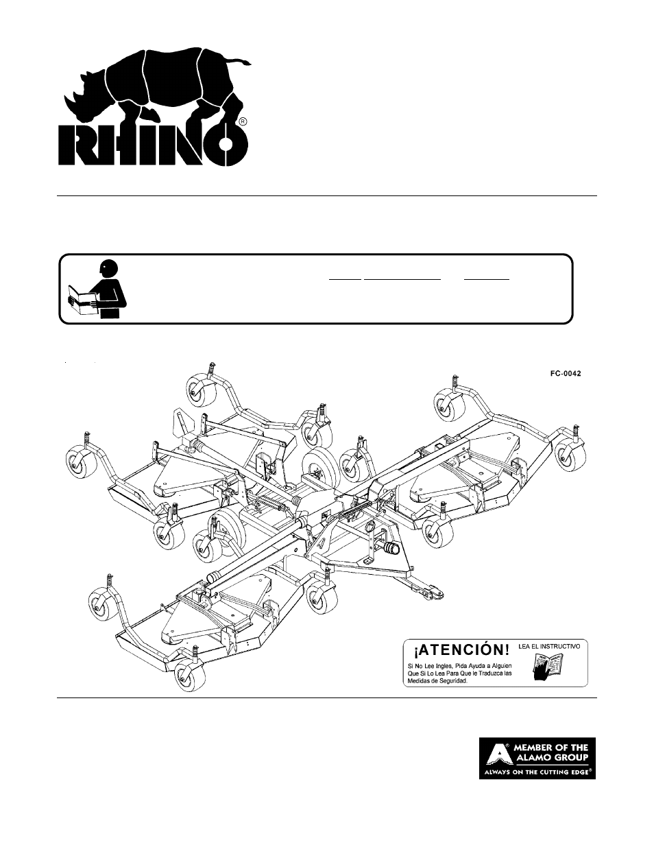
TURF FLEX
FINISHING MOWER
This Operator's Manual is an integral part of the safe operation of this machine and must
be maintained with the unit at all times. READ, UNDERSTAND, and FOLLOW the Safety
and Operation Instructions contained in this manual before operating the equipment. C01-
Cover
$0.00
Table of contents
Document Outline
- TX235
- OPERATOR’S MANUAL
- To the Owner/Operator/Dealer
- Alamo Group Ag. Division is willing to provide
- one (1) AEM Mower Safety Practices Video
- TABLE OF CONTENTS
- General Safety Instructions and Practices
- Operator Safety Instructions and Practices
- Equipment Operation Safety Instructions and Practices
- Connecting or Disconnecting Implement Safety Instructions and Practices
- Transporting Safety Instructions and Practices
- Maintenance and Service Safety Instructions and Practices
- Storage and Parking Safety Instructions and Practices
- Concluding Safety Instructions and Practices
- Decal Location
- ITEM PART NO. QTY LEVEL DESCRIPTION
- 1. 00725746 1 PELIGRO Get Manuals Translated
- 2. 00753840 3 DANGER Folding Wings
- 3. 00756004 ((4)) DANGER D/L Shield missing DO NOT OPERATE
- 4. 00756005 ((4)) DANGER Rotating Driveline
- 5. 00756059 1 DANGER Leak Detection
- 6. 00756494 1 DANGER D/L Multiple Hazard
- 7. 00758194 3 WARNING Pinch Point, Belt
- 8. 00760657 1 IMPORTANT Genuine Rhino Parts
- 9. 00773723 1 PELIGRO Rotating Driveline Translation
- 10. 00763536 3 WARNING Disengage PTO before Folding
- 11. 00769736 1 WARNING Use/Repair Shields & Guards
- 12. 00769737 3 DANGER Cutting Blades/ Thrown Objects
- 13. 02962765 2 WARNING Pinch Point/Crushing
- 14. 02967827 3 DANGER Multiple Hazard
- 15. D103 1 WARNING 540 RPM PTO
- 16. 03200347 1* REFLECT SMV
- 17. 1458392 2 REFLECT Red Reflectors
- 18. 1458393 1 REFLECT Amber Reflector
- 19. 000678 2 INSTRUCT Grease Fitting Inside
- 20. 00755691 3 INSTRUCT Lube and Blade Bolt
- 21. 00763613 1 INSTRUCT Slip Clutch Adjustment
- 22. 00763977 1 INSTRUCT Notice to Owner
- 23. D102 1 INSTRUCT Drawbar-to-PTO distance
- 24. D301 9 LOGO NAME RHINO (2-5/8 x 10-1/16)
- 25. D302 2 LOGO Rhino (4-7/8 x 6-1/2)
- 26. 00763535 5 NAME TURF FLEX
- 27. 00769825 5 MODEL TX235
- 28. 00763372 [5] SER PLT Turf Flex Serial Plate
- 29. 00763372A [5] SER PLT Left Mower TX Serial Plate
- 30. 00763372B [5] SER PLT Center Mower TX Serial Plate
- 31. 00763372C [5] SER PLT Right Mower TX Serial Plate
- 32. 00776481 1 INSTRUCT Operators Manual Inside
- 33. 00776031 1 _________ Canister, Operator’s Manual
- 34. 00767122C 1 _________ Operator’s Manual
- 35. 10058000 3 _________ Bolt
- 36. 00024100 6 _________ Flatwasher
- 37. 02959924 3 _________ Locknut
- Decal Description
- Federal Laws and Regulations
- TONGUE JACK AND WHEEL ATTACHMENT
- ITEM PART NO. QTY LEVEL DESCRIPTION
- SWIVEL AND LIFT ARM ATTACHMENT
- HYDRAULIC CYLINDER ATTACHMENT
- CASTER WHEEL ATTACHMENTS - REAR MOWER
- REAR MOWER ATTACHMENT
- DRIVELINE ATTACHMENT
- HYDRAULIC HOSE ATTACHMENT
- FIELD ASSEMBLY
- 1. Loop ends back through welded link on lock bar and then inside of braid by forming a hole 16” from end.
- 2. Adjust lengths as shown to give 8” overlap and 4” loop.
- 3. Adjust to give dimensions shown.
- 4. Secure loops by running a plastic tie through rope braids (2) to prevent slipping.
- WING DRIVELINE ATTACHMENT
- 1. Standard Equipment and Specifications
- 3. TRACTOR REQUIREMENTS
- Tractor Requirements and Capabilities
- 3.1 ROPS and Seat Belt
- 3.2 Tractor Safety Devices
- 3.3 Drawbar
- 3.4 Front End Weight
- 3.5 Power Take Off (PTO)
- 4. GETTING ON AND OFF THE TRACTOR
- 5. STARTING THE TRACTOR
- 6. CONNECTING THE MOWER TO THE TRACTOR
- 6.1 Connecting the Mower Tongue to the Tractor
- 1. The tractor must be equipped to operate at 540 RPM PTO speed and the drawbar length at 14”.
- 2. Using the parking jack, position the tongue clevis to the height of the tractor drawbar.
- 3. Board the tractor and start the engine. Back the tractor to the mower aligning the drawbar hitch hole with the mower tongue clevis. Turn off the tractor engine, place the tractor in park, and set the parking brake before dismounting.
- 4. To connect the mower, insert a 1” diameter grade 5 or 8 bolt (3) through clevis and drawbar and retain in position with a 1” locknut (4). Tighten the locknut securely but do not overtighten which could spring or break the clevis. NEVER attach ...
- 5. After connecting the mower, you can adjust tongue clevis up or down to level out mower if not level. there are four settings to choose from. First two setting can raise the mower up if mower needs to be raised to be level. There is a 2” differen...
- 6. Securely attach the mower safety chain to the tractor drawbar or drawbar support frame.
- 7. Lower the jack until the tongue is completely supported by the drawbar. Remove jack from the tongue and place on storage bracket of the mower.
- 6.2 Safety Tow Chains
- 6.3 Connecting Mower Hydraulics
- 1. With the tractor shut down and secured in position, move the hydraulic remote valve lever back and for the several times or place the hydraulic lever in the float position to relieve all hydraulic pressure. When connecting the mower hydraulic line...
- 2. Connect mower hydraulic hose to the tractor remote port. Ensure the coupler locks in place making a good connection. Different tractor models receive hydraulic lines differently. Refer to the tractor Operator’s Manual for connecting and operatin...
- 3. Ensure hydraulic hoses will not contact or become entangled with mower drivelines, do not bind when turning, or become pinched or kinked when operating, raising and lowering the mower.
- 6.1 Connecting the Mower Tongue to the Tractor
- 7. SETTING THE MOWER
- Cutting Height Adjustment
- 1. Using the tractor hydraulics, raise the mowers off the ground and support under it with secure blocking so not to let the mower drift down during maintenance.
- 2. Holding wheel and yoke assembly up, remove quick-lock pin from top of gauge wheel spindle. Position full length spacers and 1/4" spacer as required. All spacers on top of spindle tube allows for approximately 1/2" cutting height. Adjustments range...
- ROLLER ADJUSTMENT
- Cutting Height Adjustment
- 8. DRIVELINE ATTACHMENT
- 9. PRE-OPERATION INSPECTION AND SERVICE
- 10. DRIVING THE TRACTOR AND IMPLEMENT
- 11. OPERATING THE TRACTOR AND IMPLEMENT
- 12. DISCONNECTING THE MOWER FROM THE TRACTOR
- 13. MOWER STORAGE
- 14. TRANSPORTING THE TRACTOR AND IMPLEMENT
- 15. TROUBLESHOOTING GUIDE
- PROBLEM POSSIBLE CAUSE POSSIBLE REMEDY
- Worn Blade Tips Replace with Genuine RHINO blades.
- Dull Blades Sharpen blades uniformly.
- Blades unable to cut that part Slow ground speed of tractor but keep of grass pressed down by engine running at full PTO RPM. path of tractor tires or casters Cutting slower will help.
- Mowing too fast Slow down until cured.
- Drive belt loose Tighten per Instructions.
- Belt glazed/slipping Apply belt dressing or replace with
- Blade loose on Spindle. Tighten blade bolt securely.
- Conditions too wet for mowing Allow grass to dry before mowing.
- from Mower Unevenly material 540 RPM at tractor PTO, or make two
- Bunches Material passes over material. Raise the
- along Swath mower for the first pass and lower to
- PROBLEM POSSIBLE CAUSE POSSIBLE REMEDY
- PROBLEM POSSIBLE CAUSE POSSIBLE REMEDY
- Broken/bent Blade Replace with genuine RHINO blades.
- Worn/Unbalanced Blade Grind uniformly, rebalance and replace
- Bent/broken Sheave Replace parts.
- Trash Hung on Blade Clean off Blade.
- Belt Glazed Use belt dressing or replace.
- Oil on Belt Clean or replace.
- too tall or heavy maintain full PTO rpm. Cut material
- Oil on belt from overlubricate Be careful not to overlubricate.
- Belt hung up or rubbing Check belt for free travel in pulleys
- Belt Cover rubbing guide doesn’t rub any other part while
- PROBLEM POSSIBLE CAUSE POSSIBLE REMEDY
- LUBRICATION INFORMATION
- GEARBOX
- GAUGE WHEEL ASSEMBLIES
- DRIVELINE LUBRICATION
- WING DRIVELINE PROFILE LUBRICATION
- BLADE SHARPENING
- BELT ADJUSTMENT PROCEDURE
- BLADE SPINDLE SERVICE INSTRUCTIONS
- 1. Remove adjusting nut #3. Install nut #8 on end shaft.
- 2. Support spindle housing #2 under flange and drive out shaft assembly #1.
- 3. Remove bearing cups from housing. Remove lower bearing from shaft assembly using pry bars to move bearing up shaft. Once bearing has been moved 3/8" - 1/2" up shaft, lay flat bars on either side of the shaft and support across vice.or other conven...
- 4. Clean all parts and reassemble with new parts can proceed.
- 1. Press bearing cups in spindle housing.
- 2. Insert bearing cone in bottom of housing and press in bottom seal #6.
- 3. Insert shaft assembly #1 through bottom seal and bearing. Press or lightly drive shaft until it bottom against bearing.
- 4. Turn spindle over and sit on blade mount washer. Install top bearing and seal.
- 5. Install top adjusting nut #3. Adjust nut to give bearing end play of .002”-.006”. Apply Loctite 242 to nut.
- 6. Grease spindle. Until grease is forced out, top seal lip.
- STORAGE
- 1. Thoroughly clean the cutter.
- 2. Lubricate the cutter as covered in Maintenance Section.
- 3. Tighten all bolts and pins to the recommended torque.
- 4. Check the cutter for worn or damaged parts. Make replacements immediately.
- 5. Store the cutter in a clean, dry place with the cutter housing resting on blocks.
- 6. Use spray touch-up enamel where necessary to prevent rust and maintain the appearance of the cutter.
- PROPER TORQUE FOR FASTENERS
- RHINO
- LIMITED WARRANTY
- 1. LIMITED WARRANTIES
- 1.01. Rhino warrants for one year from the purchase date to the original non-commercial, governmental, or municipal purchaser (“Purchaser”) and warrants for six months to the original commercial or industrial purchaser (“Purchaser”) that the ...
- 1.02. Manufacturer will replace for the Purchaser any part or parts found, upon examination at one of its factories, to be defective under normal use and service due to defects in material or workmanship.
- 1.03. This limited warranty does not apply to any part of the goods which has been subjected to improper or abnormal use, negligence, alteration, modification, or accident, damaged due to lack of maintenance or use of wrong fuel, oil, or lubricants, ...
- 1.04. Except as provided herein, no employee, agent, Dealer, or other person is authorized to give any warranties of any nature on behalf of Manufacturer.
- 2. REMEDIES AND PROCEDURES.
- 2.01. This limited warranty is not effective unless the Purchaser returns the Registration and Warranty Form to Manufacturer within 30 days of purchase.
- 2.02. Purchaser claims must be made in writing to the Authorized Dealer (“Dealer”) from whom Purchaser purchased the goods or an approved Authorized Dealer (“Dealer”) within 30 days after Purchaser learns of the facts on which the claim is based
- 2.03. Purchaser is responsible for returning the goods in question to the Dealer.
- 2.04. If after examining the goods and/or parts in question, Manufacturer finds them to be defective under normal use and service due to defects in material or workmanship, Manufacturer will:
- (a) Repair or replace the defective goods or part(s) or
- (b) Reimburse Purchaser for the cost of the part(s) and reasonable labor charges (as determined by Manufacturer) if Purchaser paid for the repair and/or replacement prior to the final determination of applicability of the warranty by Manufacturer.
- 2.05. Purchaser is responsible for any labor charges exceeding a reasonable amount as determined by Manufacturer and for returning the goods to the Dealer, whether or not the claim is approved. Purchaser is responsible for the transportation cost for...
- 3. LIMITATION OF LIABILITY.
- 3.01. MANUFACTURER DISCLAIMS ANY EXPRESS (EXCEPT AS SET FORTH HEREIN) AND IMPLIED WARRANTIES WITH RESPECT TO THE GOODS INCLUDING, BUT NOT LIMITED TO, MERCHANTABILITY AND FITNESS FOR A PARTICULAR PURPOSE.
- 3.02. MANUFACTURER MAKES NO WARRANTY AS TO THE DESIGN, CAPABILITY, CAPACITY, OR SUITABILITY FOR USE OF THE GOODS.
- 3.03. EXCEPT AS PROVIDED HEREIN, MANUFACTURER SHALL HAVE NO LIABILITY OR RESPONSIBILITY TO PURCHASER OR ANY OTHER PERSON OR ENTITY WITH RESPECT TO ANY LIABILITY, LOSS, OR DAMAGE CAUSED OR ALLEGED TO BE CAUSED DIRECTLY OR INDIRECTLY BY THE GOODS INCLU...
- 3.04. NO ACTION ARISING OUT OF ANY CLAIMED BREACH OF THIS WARRANTY OR TRANSACTIONS UNDER THIS WARRANTY MAY BE BROUGHT MORE THAN TWO (2) YEARS AFTER THE CAUSE OF ACTION HAS OCCURRED.
- 4. MISCELLANEOUS.
- 4.01. Proper Venue for any lawsuits arising from or related to this limited warranty shall be only in Guadalupe County, Texas.
- 4.02. Manufacturer may waive compliance with any of the terms of this limited warranty, but no waiver of any terms shall be deemed to be a waiver of any other term.
- 4.03. If any provision of this limited warranty shall violate any applicable law and is held to be unenforceable, then the invalidity of such provision shall not invalidate any other provisions herein.
- 4.04. Applicable law may provide rights and benefits to purchaser in addition to those provided herein.