Front panel connector: jfp1, Nmi button: jpbtn1, Lcd module connector: jlcd1 – MSI P1-109N-L70 User Manual
Page 35
2-15
Hardware Setup
PIN
SIGNAL
DESCRIPTION
1
HD_LED +
Hard disk LED pull-up
2
FP PWR/SLP
MSG LED pull-up
3
HD_LED -
Hard disk active LED
4
FP PWR/SLP
MSG LED pull-up
5
RST_SW -
Reset Switch low reference pull-down to GND
6
PWR_SW +
Power Switch high reference pull-up
7
RST_SW +
Reset Switch high reference pull-up
8
PWR_SW -
Power Switch low reference pull-down to GND
9
RSVD_DNU
Reserved. Do not use.
JFP1 Pin Definition
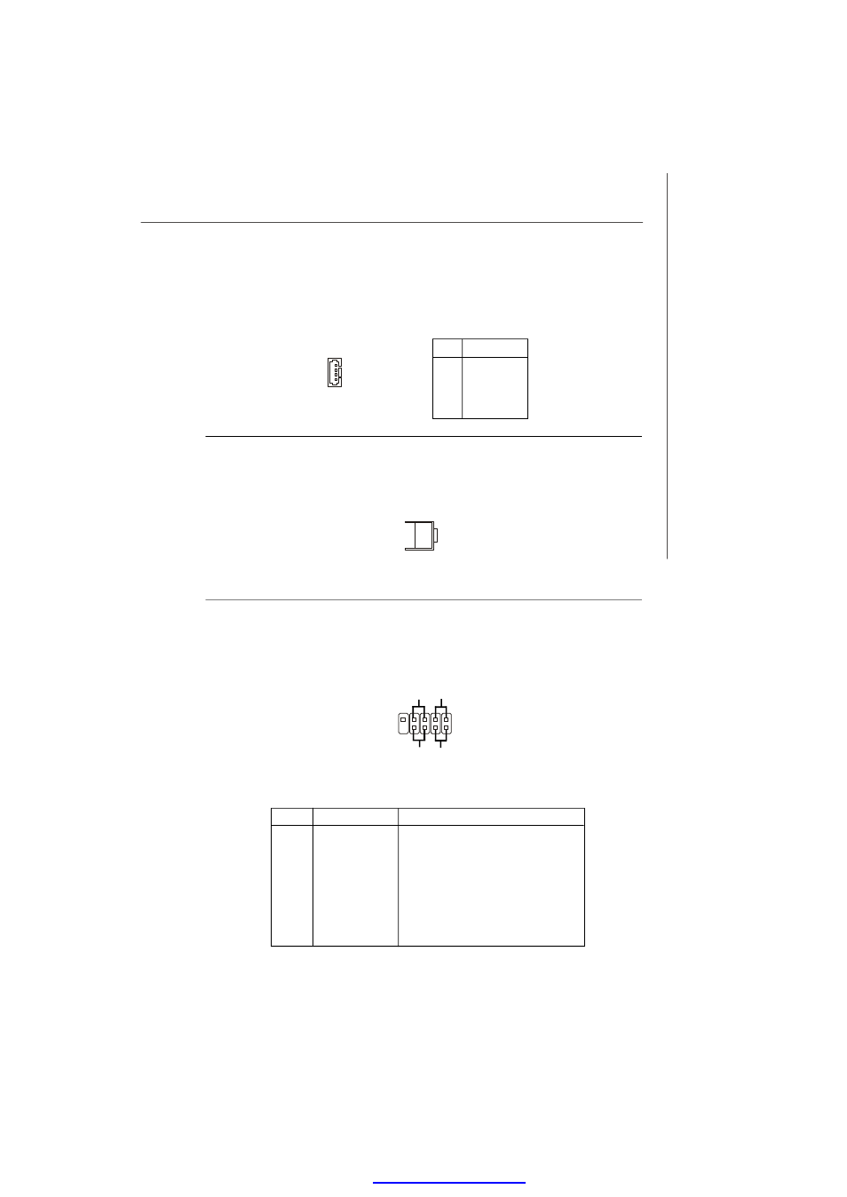
Front Panel Connector: JFP1
This connector is for electrical connection to the front panel switches and LEDs and
is compliant with Intel
®
Front Panel I/O Connectivity Design Guide.
NMI Button: JPBTN1
W hen the Operating System suffers from critical errors and consequently hangs,
users may press this NMI (Non Maskable Interrupt) button to log the system errors.
JPBTN1
2
1
10
9
JFP1
HDD
LED
Reset
Switch
Power
LED
Power
Switch
+
+
+
-
-
-
-
+
LCD Module Connector: JLCD1
This connector is used to connect TTL UART LCD Module.
PIN
SIGNAL
1
+5V
2
RX
3
GND
4
TX
Pin Definition
1
JLCD1
PDF created with pdfFactory Pro trial versi