Connections, System connection diagram – Aiphone IS SERIES 834168 C P0811JZ User Manual
Page 6
6
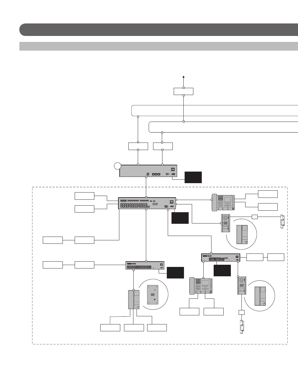
CONNECTIONS
System connection diagram
The following is an example of standard (IP) system connection diagram.
Refer to page 9 to 26 for details about each unit connection.
*
IP
IS-IPC
*1
IS-CCU
IS-RCU
IS-SCU
IS-RS
IS-RS
IS-RS
IS-MV
IS-DV/IS-DVF
/IS-SS
IS-DV/IS-DVF
/IS-SS
IS-MV
PT
PT
IS-SS
IS-PU-UL
IS-PU-S
IS-PU-UL
IS-PU-S
IS-PU-UL
IS-PU-S
IS-PU-UL
IS-PU-S
Local system
(Max.8)
(Max. 8)
(Max. 4)
(Max. 4)
(Max. 2)
(Max. 4)
(Max. 1)
(Max. 30)
To Internet/WAN
Monitor
Monitor
Recorder
Recorder
Broadband
router
Call button
Strobe light
Switch (Hub)
PBX / Telephone
EL-12S
Electric door strike
EL-12S
Electric door
strike
AC
transformer
AC
transformer
PA speaker
PA amplifi er
CD player
Timer
PA amplifi er
PA amplifi er
PA speaker
PA speaker
8Ω speaker
*1: An IP control unit (IS-IPC) is needed to connect a local system to a standard (IP) system.
or
or
or
or
and
/or
and
/or
and
/or
- VC-6M (8 pages)
- TA-24H (10 pages)
- JK-1MED (17 pages)
- MID-POWER MP-1S (4 pages)
- DOOR RELEASE RELAY MODULE RY-24L (3 pages)
- PANTILT DOOR STATION MY-DG/A (4 pages)
- KB-DAR (2 pages)
- AN-8050DS (2 pages)
- JKW-IP (8 pages)
- JKW-IP (56 pages)
- FK1629 B 0811YZ (31 pages)
- JA-2MECD (12 pages)
- MK-1MD/A (6 pages)
- LAM-1 (4 pages)
- JB-2MD (16 pages)
- JB-2HD (14 pages)
- LAF-3B (4 pages)
- VIDEO ENTRY SYSTEM JKW-IP (8 pages)
- AT-406 (2 pages)
- DOOR STATION IC-D3 (4 pages)
- ROAMER WP100A (12 pages)
- LEF-10S (12 pages)
- LAM-1S (1 page)
- JK-DVF-AC (13 pages)
- GT-2H-L (26 pages)
- IE-2AD(U) (4 pages)
- JF-1FD (8 pages)
- LAF-3A (6 pages)
- COLOR SENTRY KAS-1ED (8 pages)
- KAH-24 (10 pages)
- MK-2HCD (2 pages)
- IE-1AD(U) (4 pages)
- MJS-1AD/A (6 pages)
- JF-2HD (16 pages)
- IPW-1A (4 pages)
- IP-EWST-POE (4 pages)
- C-123LW (4 pages)
- SBX-AXDV30 (1 page)
- MCH-U (4 pages)
- GFO-1DL (5 pages)
- JK-DVF (8 pages)
- IE VIDEO DOOR STATION MF-D (4 pages)
- GFW-VBC (4 pages)
- GT-1D (8 pages)
- FK1628 B P0811JZ (16 pages)