Connections – Aiphone IS SERIES 834168 C P0811JZ User Manual
Page 11
11
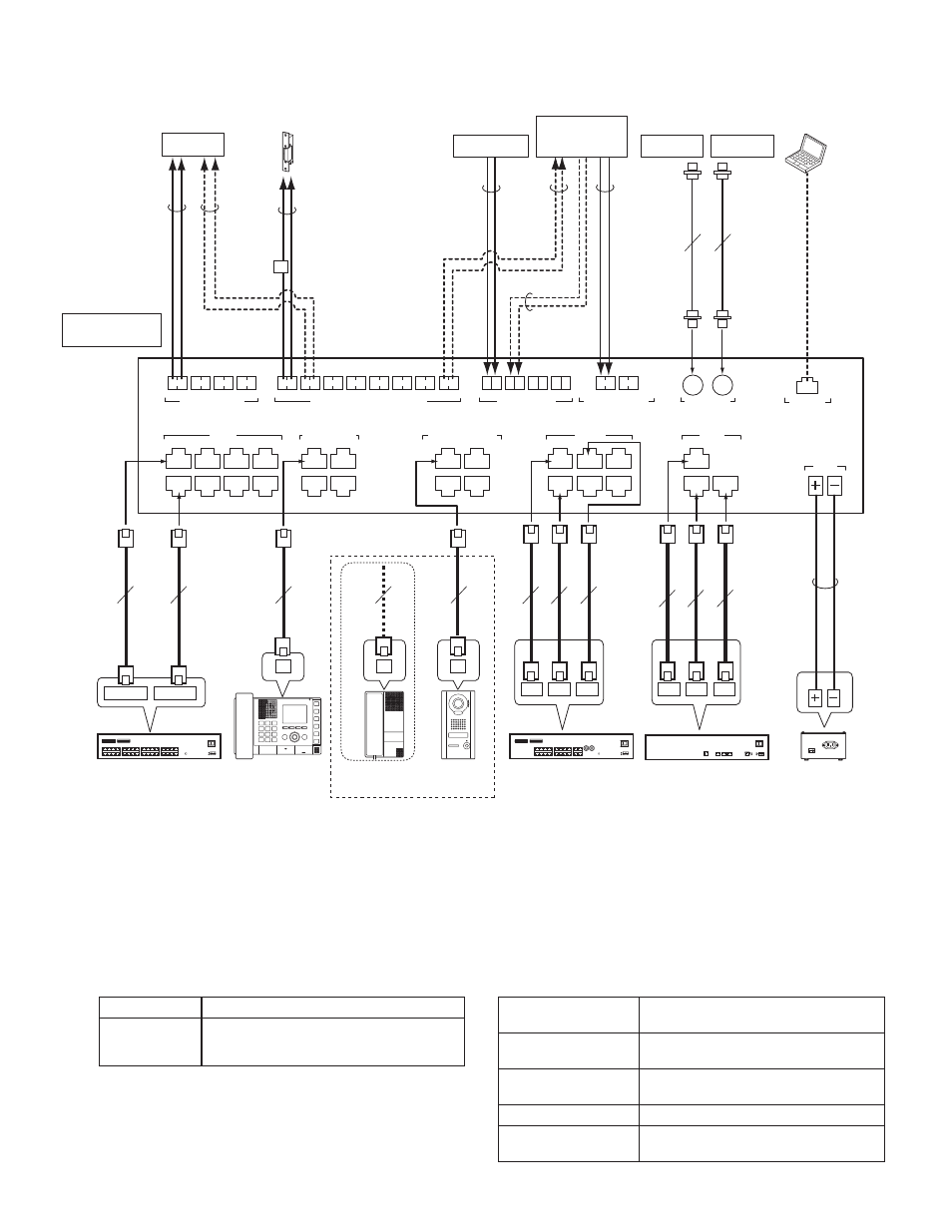
■ Connections
1CX1
1CX2
M1
M2
1MX1
1MX2
1MX3
2MX1
2MX2
2MX3
M3
M4
D1
D2
IP1
LAN
IP2
IP3
D3
D4
2CX1
2CX2
3CX1
3CX2
4CX1
4CX2
P1
P2
P3
P4
L1
L2
L3
L4
L5
L6
L7
L8
S1 E S2 E S3 E S4 E
IS-RCU
MASTER STATION
IS-SCU
IS-IPC
DC48V
DOOR/SUB STATION
VIDEO/AUDIO
PA OUTPUT (600Ω)
CONTACT INPUT
CHIME INPUT (600Ω)
ETHERNET
VIDEO OUTPUT
CONTACT OUTPUT (AC/DC24V 0.5A)
B2
B1
V1
V2
CAT5e/6
200m
(650')
CAT5e/6
200m
(650')
CAT5e/6
300m
(980')
CAT5e/6
300m
(980')
10m (33')
15m
(50')
200m
(650')
CAT5e/6
150m
(490')
Coax
15m (50')
NTSC
15m (50')
NTSC
*2
*3
*4
*1
D
C
2C
M
IP1
IP2
IP3
MX1 MX2 MX3
Coax
CX1/IP1
CX2/IP2
PT
BNC
connector
BNC
connector
BNC
connector
BNC
connector
φ0.65-1.2mm
(22-16 AWG)
φ0.65-1.2mm
(22-16 AWG)
15m (50')
φ0.65-1.2mm
(22-16 AWG)
15m (50')
φ0.8-1.2mm
(20-16 AWG)
NP
NP
P
P
2C
2C
2C
*5
NP
2C
φ0.65-1.2mm
(22-16 AWG)
15m (50')
P
2C
φ0.65-1.2mm
(22-16 AWG)
15m (50')
NP
2C
φ0.65-1.2mm
(22-16 AWG)
NP
2C
φ0.65-1.2mm
(22-16 AWG)
CAT5e/6 (x3)
CAT5e/6 (x3)
*1: This connection is needed when a PA amplifi er that needs a trigger input is connected. (Up to AC/DC 24V 0.5A)
*2: This connection is needed when a sound source etc. that needs a trigger input is connected. (Up to AC/DC 24V 0.5A) Connect a timer to the
CONTACT INPUT terminals when an external sound source device (CD player etc.) that does not have a timer function is connected.
*3: This connection is needed when a sound source that has a trigger output is connected.
*4: Refer to the SETTING MANUAL for connection and settings.
*5: Do not install two power supplies in parallel to a single input. Be sure to connect a single power supply unit to a control unit.
*6: Do not use an external sound source as background music. If the background music is interrupted by another performance during chime paging,
the chime paging will not be restored after the performance ends.
*7: Outputs images only from a video door station connected to this unit.
*8: Output specifi cations
Output method
N/O or N/C dry closure contact
Voltage between
terminals
24V AC, 0.5A (resistive load)
24V DC, 0.5A (resistive load)
Minimum overload (AC/DC): 100mV, 0.1mA
NOTES:
Do not use the unoccupied terminals and ports for other purposes.
•
In order to prevent miswiring, label both ends of each cable with
•
the unit and terminal names to which they are to be connected.
For connecting other manufacturer’s products, refer to the
•
instruction manuals for those products.
The illustration of the unit’s front panel differs from the actual
•
one. This is for simplifying the connection diagram.
*9: Input specifi cations
Input method
N/O or N/C dry closure contact (start
signal only detection method)
Detection confi rmation
time
100 ms or more
Contact resistance
During N/O dry closure: Less than 700 Ω
During N/C dry closure: At least 4 k Ω
Terminal short current
Less than 10 mA
Voltage between
terminals
Less than 5 V DC (when open between
terminals)
Monitor 1,
Recorder 1
Monitor 2,
Recorder 2
Door station
(IS-DV/IS-DVF/
IS-SS)
Power supply unit
(IS-PU-UL/IS-PU-S)
Master station
(IS-MV)
Contact output
*8
(Electric door strike, strobe light, etc.)
PA output
(50mVrms, 600Ω)
PA amplifi er
External sound
source such as
CD player, etc.
*6
Chime input (50mVrms, 600Ω)
Contact input
*9
Sensor, etc.
Room sub control unit
(IS-RCU)
Add-on control unit
(IS-SCU)
PC for setting
the system
Room sub station
(IS-RS)
IP control unit
(IS-IPC)
or
(non-shielded)
(non-shielded) (non-shielded)
(non-shielded)
(non-shielded)
(non-shielded)
(non-shielded)
AC
transformer
NP: Non-polarized
P: Polarized
*7
*7