Warning – Howard HI-110 Network Transformer User Manual
Page 17
Document 2.4.128, Revision 2
August, 2012
17
Network Transformer Instruction Manual
Operation of the three-position mag-break switch is
similar to that of the three-position non-interrupting
switch. Before attempting to operate the mag-break
switch, verify that the network protector is in the
open position.
Sequential Grounding Provisions
When specified, the three-position primary
disconnect and grounding switch can be supplied
with two additional positions to allow for sequential
grounding of the primary feeders. Typical switch
operation is described in Table 2 below; however,
other user-specified switch characteristics are
available. Markings on the switch handle indicate
switch position. The switch may be operated in either
a clockwise or counterclockwise direction.
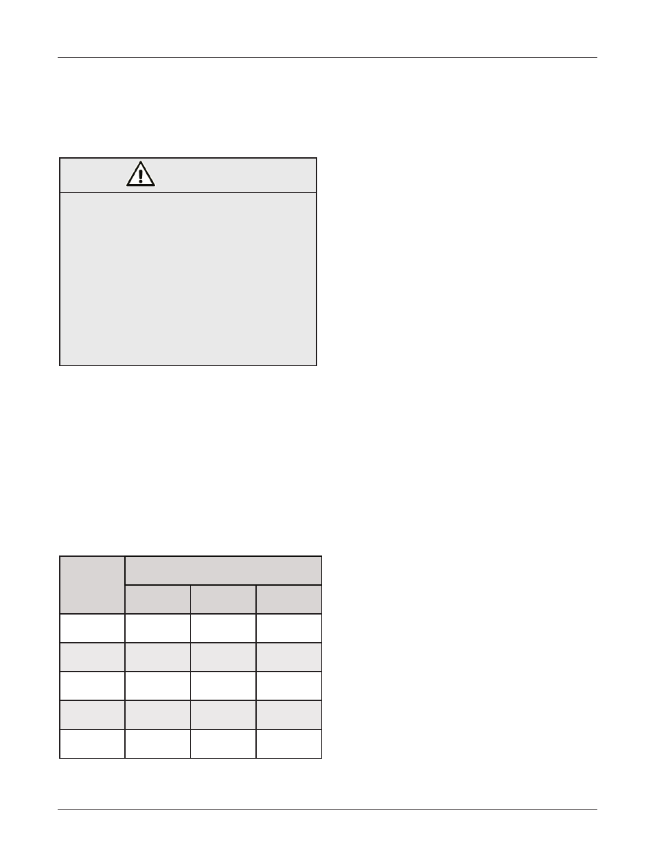
Table 2: Sequential Grounding Switch Operation
Switch
Position
Primary Feeder Connections
A Phase
B Phase
C Phase
A
Grounded
Open
Open
AB
Grounded
Grounded
Open
GROUND
Grounded
Grounded
Grounded
OPEN
Open
Open
Open
CLOSED
Closed
Closed
Closed
Phase Sequence Identification Provisions
Optional phase sequence identification provisions
(also known as “phasing tubes”) are provided
when specified to allow determination of the phase
sequence of incoming primary feeders. Phasing
tubes are located on the switch chamber cover and
are positioned to allow phasing probes to be inserted
and make electrical contact with live portions of the
switch bushings. Pipe plugs or caps are provided to
seal phasing tubes when not in use.
Network Protector
Howard network transformers are usually supplied
with network protector mounting provisions designed
according to user specifications. These provisions
typically consist of a secondary throat with mounting
holes, guide pins and gasket. A steel shipping guard
is installed over the secondary throat to protect the
secondary bushings, connectors and throat flange
from damage during shipment and storage.
The network protector should be installed, operated
and maintained by the user according to the
instructions provided by the network protector
manufacturer.
Other Switching and Protective Devices
Contact the Howard Industries Transformer Division
for information related to any other switching
or protection options not discussed in these
instructions.
WARNING
FAILURE TO FOLLOW THE INSTRUCTIONS
BELOW COULD RESULT IN DEATH OR SERIOUS
PERSONAL INJURY AND MAY ALSO RESULT IN
DAMAGE TO THE EQUIPMENT.
Although the electrical interlock system should
prevent unsafe operation of the primary
switch, the operator should verify that the
transformer is disconnected from the primary
feeder and that the network protector is in the
open position.