Warning – Howard HI-110 Network Transformer User Manual
Page 16
Document 2.4.128, Revision 2
August, 2012
16
Network Transformer Instruction Manual
Primary Disconnect and Grounding Switch
Network transformers are normally supplied with a
three-position primary disconnect switch (sometimes
called a “network switch”), which is housed in a fluid-
filled chamber welded to the main tank below the
primary terminal chamber. Primary switches can be
designed as a non-interrupting switch suitable only
for completely de-energized operation, or designed
to interrupt magnetizing current only (Sometimes
called a “mag-break switch.”). An external, pad-
lockable switch operating handle is provided with
a mechanical latching mechanism to prevent
accidental movement of the switch.
Three-position switches are designed with an
operating sequence of OPEN, CLOSED, and
GROUND. In the OPEN position the primary feeder
is disconnected from the transformer and from
ground. In the CLOSED position the primary feeder
is connected to the transformer. In the GROUND
position the primary feeder is solidly grounded, while
the transformer is disconnected and not grounded by
the grounding switch.
Unless otherwise specified, network transformers are
shipped from the factory with the primary disconnect
and grounding switch set to the CLOSED position.
Contact the Howard Industries Transformer Division
to inquire about other switch configurations and
options that may be available.
Three-Position Non-Interrupting Primary Disconnect
and Grounding Switch
The non-interrupting switch is suitable for use only
when the transformer is totally de-energized. An
electrical interlock is normally provided to prevent
operation of the switch while the transformer is
energized from either the high-voltage or low-voltage
side.
Before attempting to operate the non-interrupting
primary switch, verify that the transformer is not
energized from either the high-voltage or low-voltage
side. Use the following procedure to move the switch
from the OPEN to the CLOSED position.
1. Operate the blocking toggle pin.
2. Pull the mechanical locking pin on the handle.
3. Rotate the handle until the mechanical locking
pin engages in the CLOSED position.
Use the following procedure to move the switch from
the CLOSED to the GROUND position.
1. Operate the blocking toggle pin.
2. Pull the mechanical locking pin on the handle.
3. Rotate the handle until the mechanical locking
pin engages in the GROUND position.
Three-Position Mag-Break Primary Disconnect and
Grounding Switch
The mag-break switch is designed to operate when
only magnetizing current is present and is prevented
from operating while the network protector is in
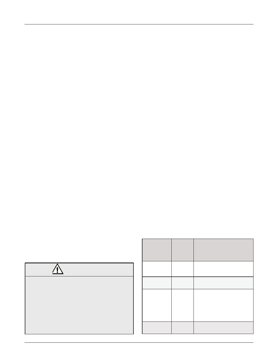
the closed position. The switch is equipped with an
electric interlock system, which permits operation
of the switch according to the parameters listed
in Table 1 below. The interlock system requires
a source of power that is independent of the
associated network transformer and an auxiliary
contact on the network protector. The interlock
system will lock if it looses its independent power
source.
Table 1: Mag-Break Primary Switch Operation
Primary
Feeder
Status
Network
Protector
Position
Switch
Operation
De-energized
OPEN
Switch may be operated to
any position
De-energized CLOSED Switch cannot be operated
Energized
OPEN
Switch may operate be-
tween CLOSED and OPEN
positions. Switch cannot
operate between CLOSED
and GROUND positions.
Energized
CLOSED Switch cannot be operated.
FAILURE TO FOLLOW THE INSTRUCTIONS BELOW
COULD RESULT IN DEATH OR SERIOUS PERSONAL
INJURY AND MAY
ALSO RESULT IN
DAMAGE TO
THE EQUIPMENT.
Although the electrical interlock system should
prevent unsafe operation of the primary switch,
the operator should verify that the transformer is
disconnected from the primary feeder and that
the network protector is in the OPEN position.
WARNING