Ds508f2 – Cirrus Logic EP7312 User Manual
Page 35
DS508F2
Copyright Cirrus Logic, Inc. 2011
(All Rights Reserved)
35
EP7312
High-Performance, Low-Power System on Chip
118
D[20]
1
Low
I/O
Data I/O
119
A[19]/DRA[8]
1
Low
O
System byte address /
SDRAM address
120
D[19]
1
Low
I/O
Data I/O
121
A[18]/DRA[9]
1
Low
O
System byte address /
SDRAM address
122
D[18]
1
Low
I/O
Data I/O
123
VDDIO
Pad Pwr
Digital I/O power, 3.3 V
124
VSSIO
Pad Gnd
I/O ground
125
nTRST
I
JTAG async reset input
126
A[17]/DRA[10]
1
Low
O
System byte address /
SDRAM address
127
D[17]
1
Low
I/O
Data I/O
128
A[16]/DRA[11]
1
Low
O
System byte address /
SDRAM address
129
D[16]
1
Low
I/O
Data I/O
130
A[15]/DRA[12]
1
Low
O
System byte address /
SDRAM address
131
D[15]
1
Low
I/O
Data I/O
132
A[14]/DRA[13]
1
Low
O
System byte address /
SDRAM address
133
D[14]
1
Low
I/O
Data I/O
134
A[13]/DRA[14]
1
Low
O
System byte address /
SDRAM address
135
D[13]
1
Low
I/O
Data I/O
136
A[12]
1
Low
O
System byte address
137
D[12]
1
Low
I/O
Data I/O
138
A[11]
1
Low
O
System byte address
139
VDDIO
Pad Pwr
Digital I/O power, 3.3 V
140
VSSIO
Pad Gnd
I/O ground
141
D[11]
1
Low
I/O
Data I/O
142
A[10]
1
Low
O
System byte address
143
D[10]
1
Low
I/O
Data I/O
144
A[9]
1
Low
O
System byte address
145
D[9]
1
Low
I/O
Data I/O
146
A[8]
1
Low
O
System byte address
147
D[8]
1
Low
I/O
Data I/O
148
A[7]
1
Low
O
System byte address
149
VSSIO
Pad Gnd
I/O ground
150
D[7]
1
Low
I/O
Data I/O
151
nBATCHG
I
Battery changed sense input
152
nEXTPWR
I
External power supply sense
input
153
BATOK
I
Battery OK input
154
nPOR
Schmitt
I
Power-on reset input
155
nMEDCHG/nBROM
I
Media change interrupt input /
internal ROM boot enable
156
nURESET
Schmitt
I
User reset input
157
VDDOSC
Oscillator Power
Oscillator power in, 2.5 V
158
MOSCIN
I
Main oscillator input
159
MOSCOUT
O
Main oscillator output
160
VSSOSC
Oscillator Ground
Oscillator Ground
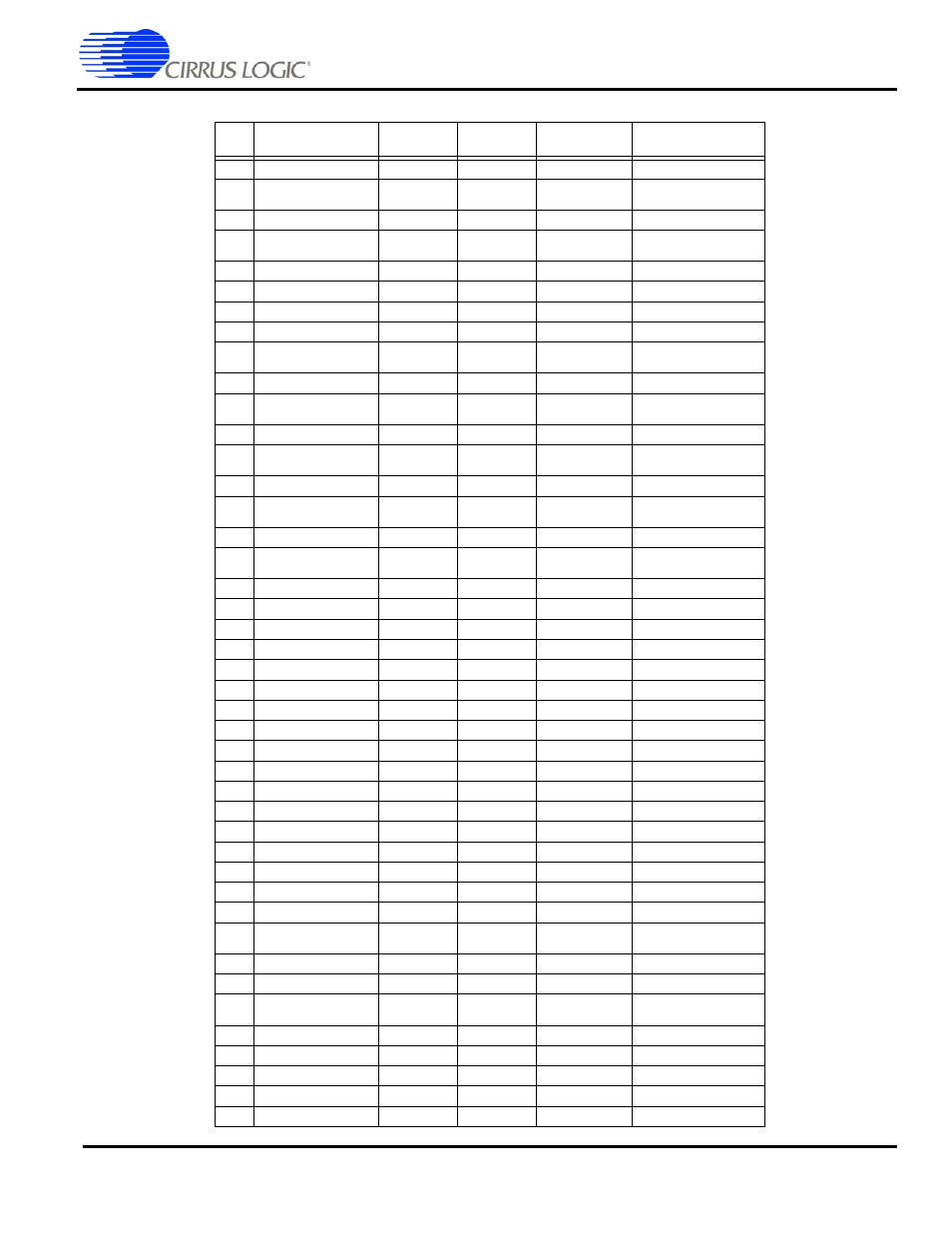
Table 20. 208-Pin LQFP Numeric Pin Listing (Continued)
Pin
No.
Signal
Strength
†
Reset
State
Type
Description