Cs8421 – Cirrus Logic CS8421 User Manual
Page 15
DS641F6
15
CS8421
CS8421
CS8421
VD
VL
Serial
Audio
Source
ILRCK
ISCLK
SDIN
BYPASS
+2.5 V
+3.3 V or +5.0 V
0.1
F
0.1
F
Serial
Audio
Input
Device
OLRCK
OSCLK
SDOUT
XTI
XTO
RST
SRC_UNLOCK
SAOF
TDM_IN
Hardware Control
Settings
Crystal /Clock
Source
GND
SAIF
MS_SEL
GND
MCLK_OUT
To external
hardware
47 k
*
**
***
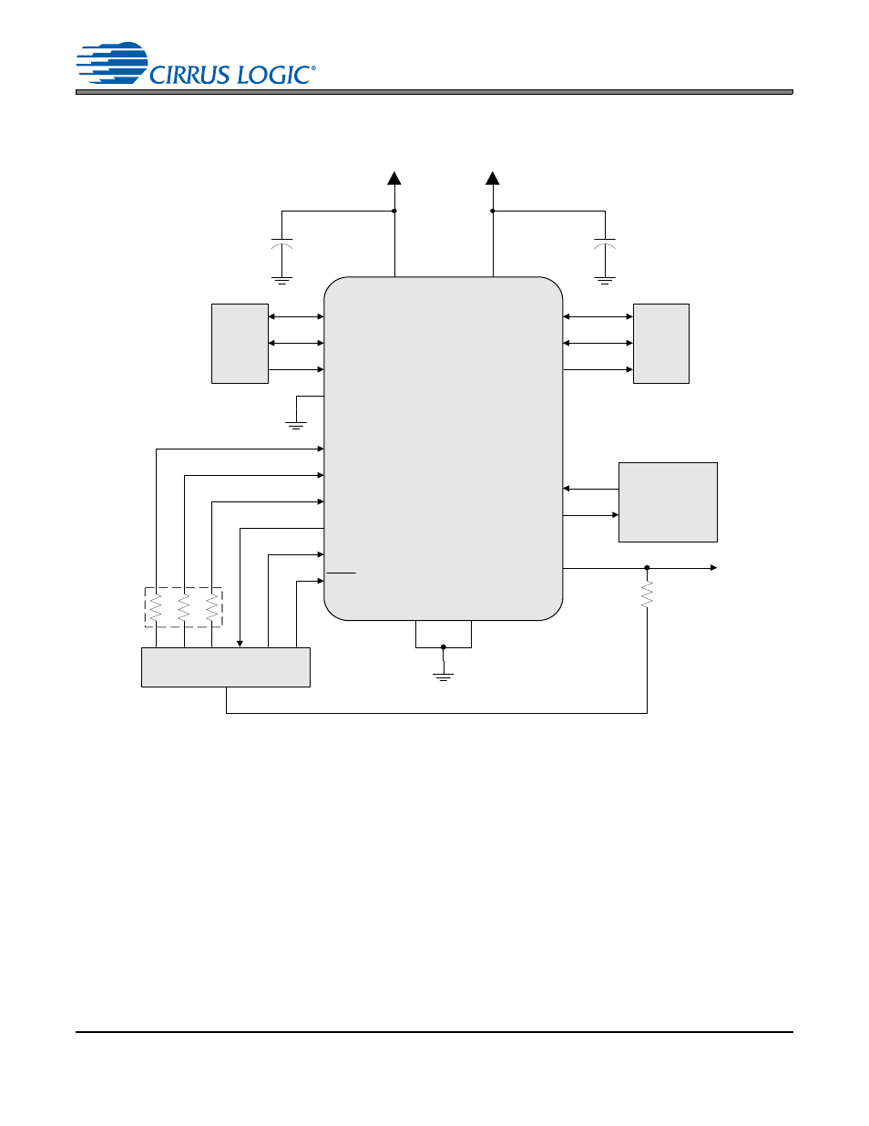
Figure 6. Typical Connection Diagram, Master and Slave Modes
* The connection (VL or GND) and value of these three resistors determines the mode of operation for the input
and output serial ports as described in
Table 1 Serial Audio Port Master/Slave and Clock Ratio Select Start-Up Op-
, and
Table 2, “Serial Audio Input Port Start-Up Options (SAIF),” on page 18
and
Audio Output Port Start-Up Options (SAOF),” on page 18
.
** MCLK_OUT pin should be pulled high through a 47 k
resistor if an MCLK output is not needed.
*** This pin must not be pulled high. See
- CobraNet (147 pages)
- CS4961xx (54 pages)
- CS150x (8 pages)
- CS1501 (16 pages)
- CS1601 (2 pages)
- CS1601 (16 pages)
- CS1610 (16 pages)
- CRD1610-8W (24 pages)
- CRD1611-8W (25 pages)
- CDB1610-8W (21 pages)
- CS1610A (18 pages)
- CDB1611-8W (21 pages)
- CDB1610A-8W (21 pages)
- CDB1611A-8W (21 pages)
- CRD1610A-8W (24 pages)
- CRD1611A-8W (25 pages)
- CS1615 (16 pages)
- AN403 (15 pages)
- AN401 (14 pages)
- AN400 (15 pages)
- AN375 (27 pages)
- AN376 (9 pages)
- CRD1615-8W (22 pages)
- CRD1616-8W (23 pages)
- AN402 (14 pages)
- AN404 (15 pages)
- CRD1615A-8W (21 pages)
- CS1615A (16 pages)
- CS1630 (56 pages)
- AN374 (35 pages)
- AN368 (80 pages)
- CRD1630-10W (24 pages)
- CRD1631-10W (25 pages)
- CS1680 (16 pages)
- AN405 (13 pages)
- AN379 (31 pages)
- CRD1680-7W (31 pages)
- AN335 (10 pages)
- AN334 (6 pages)
- AN312 (14 pages)
- AN Integrating CobraNet into Audio Products (16 pages)
- CobraNet Audio Routing Primer (9 pages)
- Bundle Assignments in CobraNet Systems (3 pages)
- CS2300-01 (3 pages)
- CS2000-CP (38 pages)