Typical connection diagrams, Cs8421 – Cirrus Logic CS8421 User Manual
Page 14
14
DS641F6
CS8421
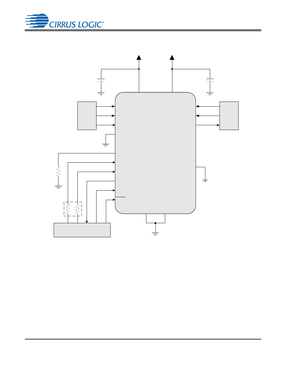
3. TYPICAL CONNECTION DIAGRAMS
CS8421
VD
VL
Serial
Audio
Source
ILRCK
ISCLK
SDIN
BYPASS
+2.5 V
+3.3 V or +5.0 V
0.1
F
0.1
F
Serial
Audio
Input
Device
OLRCK
OSCLK
SDOUT
XTI
RST
SRC_UNLOCK
SAOF
TDM_IN
Hardware Control
Settings
GND
SAIF
MS_SEL
GND
**
1 k
*
***
Figure 5. Typical Connection Diagram, No External Master Clock
* When no external master clock is supplied to the part, both input and output must be set to Slave Mode for the
part to operate properly. This is done by connecting the MS_SEL pin to ground through a resistance of 0
to 1 k
Table 1, “Serial Audio Port Master/Slave and Clock Ratio Select Start-Up Options (MS_SEL),”
** The connection (VL or GND) and value of these two resistors determines the mode of operation for the input and
output serial ports as described in
and
.
*** This pin must not be pulled high. See
- CobraNet (147 pages)
- CS4961xx (54 pages)
- CS150x (8 pages)
- CS1501 (16 pages)
- CS1601 (2 pages)
- CS1601 (16 pages)
- CS1610 (16 pages)
- CRD1610-8W (24 pages)
- CRD1611-8W (25 pages)
- CDB1610-8W (21 pages)
- CS1610A (18 pages)
- CDB1611-8W (21 pages)
- CDB1610A-8W (21 pages)
- CDB1611A-8W (21 pages)
- CRD1610A-8W (24 pages)
- CRD1611A-8W (25 pages)
- CS1615 (16 pages)
- AN403 (15 pages)
- AN401 (14 pages)
- AN400 (15 pages)
- AN375 (27 pages)
- AN376 (9 pages)
- CRD1615-8W (22 pages)
- CRD1616-8W (23 pages)
- AN402 (14 pages)
- AN404 (15 pages)
- CRD1615A-8W (21 pages)
- CS1615A (16 pages)
- CS1630 (56 pages)
- AN374 (35 pages)
- AN368 (80 pages)
- CRD1630-10W (24 pages)
- CRD1631-10W (25 pages)
- CS1680 (16 pages)
- AN405 (13 pages)
- AN379 (31 pages)
- CRD1680-7W (31 pages)
- AN335 (10 pages)
- AN334 (6 pages)
- AN312 (14 pages)
- AN Integrating CobraNet into Audio Products (16 pages)
- CobraNet Audio Routing Primer (9 pages)
- Bundle Assignments in CobraNet Systems (3 pages)
- CS2300-01 (3 pages)
- CS2000-CP (38 pages)