6 digital filter, 7 clock generator, 6 digital filter 1.7 clock generator – Cirrus Logic CS5528 User Manual
Page 42
CS5521/22/23/24/28
42
DS317F8
1.6 Digital Filter
The CS5521/22/23/24/28 have eight different lin-
ear phase digital filters which set the output word
rates (OWRs) shown in Table 3. These rates as-
sume that XIN is 32.768 kHz. Each of the filters
has a magnitude response similar to that shown in
Figure 18. The filters are optimized to settle to full
accuracy every conversion and yield better than
80 dB rejection for both 50 and 60 Hz with output
word rates at or below 15.0 Sps.
The converter’s digital filters scale with XIN. For
example with an output word rate of 15 Sps, the fil-
ter’s corner frequency is typically 12.7 Hz using a
32.768 kHz clock. If XIN is increased to
65.536 kHz the OWR doubles and the filter’s cor-
ner frequency moves to 25.4 Hz.
1.7 Clock Generator
The CS5521/22/23/24/28 include a gate which can
be connected with an external crystal to provide the
master clock for the chip. The chips are designed to
operate using a low-cost 32.768 kHz “tuning fork”
type crystal. One lead of the crystal should be con-
nected to XIN and the other to XOUT. Lead lengths
should be minimized to reduce stray capacitance.
Note that the oscillator circuit will also operate
with a 100 kHz “tuning fork” type crystal.
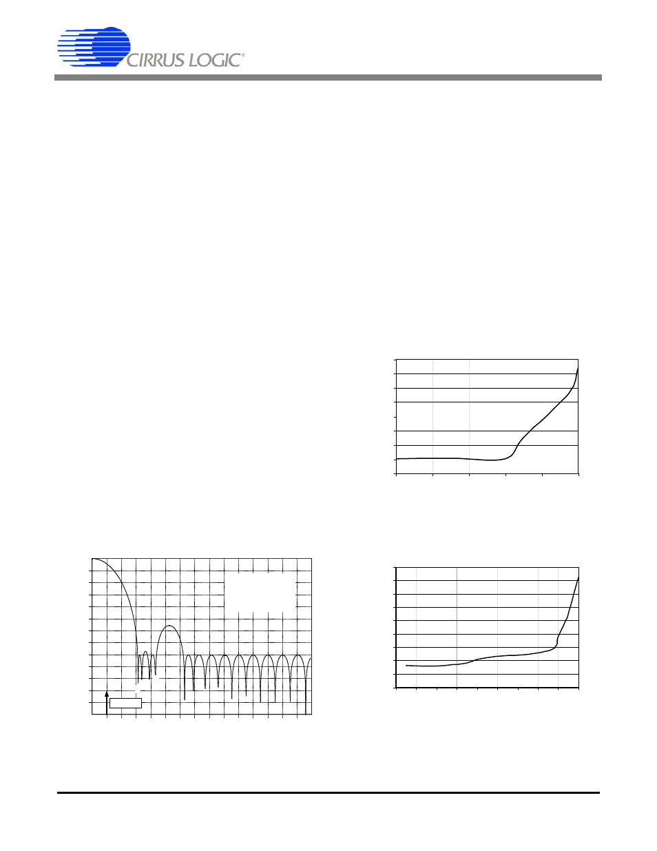
The converters will operate with an external
(CMOS compatible) clock with frequencies up to
130 kHz (CS5521/23) or 200 kHz (CS5522/24/28).
Figures 19 and 20 detail the CS5521/23 and
CS5522/24/28’s performance (respectively) at in-
creased clock rates.
The 32.768 kHz crystal is normally specified as a
time-keeping crystal with tight specifications for
both initial frequency and for drift over tempera-
ture. To maintain excellent frequency stability,
these crystals are specified only over limited oper-
ating temperature ranges (i.e. -10° C to +60° C).
However, applications with the
CS5521/22/23/24/28 don’t generally require such
tight tolerances.
0
-10
-20
-30
-40
-50
-60
-70
-80
-90
-100
-110
-120
-130
0
Atte
nuati
on (dB)
1
2
3
4
5
6
7
8
9
10
11 12
13
14
15
for OWR = 15.0 Sps
f1 = 47.5 Hz
f2 = 65.5 Hz
fS/2 = XIN/4
f1
f2
15 Sps
Figure 18. Filter Response (Normalized to Output Word
Rate = 15 Sps)
0.0004
0.0006
0.0008
0.001
0.0012
0.0014
0.0016
0.0018
0.002
30
50
70
90
110
130
XIN (kHz)
Li
n
e
ar
it
y
E
rr
o
r (
%
F
S
)
Figure 19. Typical Linearity Error for CS5521/23
0.0004
0.0005
0.0006
0.0007
0.0008
0.0009
0.001
0.0011
0.0012
0.0013
20
40
60
80
100 120 140 160 180 200
XIN (kHz)
Li
n
e
ar
it
y Er
ro
r (
%
F
S
)
Figure 20. Typical Linearity Error for CS5522/24/28