2 system calibration – Cirrus Logic CS5528 User Manual
Page 32
CS5521/22/23/24/28
32
DS317F8
offset to occur in the 25 mV, 55 mV, and 100 mV
ranges, the AIN- pin must be at the proper com-
mon-mode voltage as specified in ‘Common Mode
+Signal AIN+/-’ specification in the Analog Input
section (if AIN- = 0 V, NBV must be between -
1.8 V to -2.5 V). For self calibration of offset in the
1.0 V, 2.5 V, and 5 V ranges, the inputs of the mod-
ulator are connected together and then routed to the
VREF- pin as shown in Figure 12.
For self calibration of gain, the differential inputs
of the modulator are connected to VREF+ and
VREF- as shown in Figure 13. For any input range
other than the 2.5 V range, the converter’s gain er-
ror can not be completely calibrated out when using
self calibration. This is due to the lack of an accu-
rate full-scale voltage internal to the chips. The
2.5 V range is an exception because the external
reference voltage is 2.5 V nominal and is used as
the full-scale voltage. In addition, when self cali-
bration of gain is performed in the 25 mV, 55 mV,
and 100 mV input ranges, the instrumentation am-
plifier’s gain is not calibrated. These two factors
can leave the converters with a gain error of up to
±20% after self calibration of gain. Therefore, a
system gain calibration is required to get better ac-
curacy, except for the 2.5 V range.
1.3.2 System Calibration
For the system calibration functions, the user must
supply the calibration signals to the converter which
represent ground and full scale. When a system offset
calibration is performed, a ground-referenced signal
must be applied to the converters. See
Figures 14 and 15.
As shown in Figures 16 and 17, the user must input
a signal representing the positive full-scale point to
AIN+
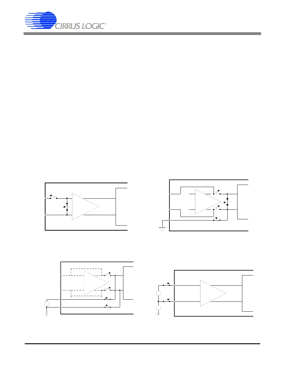
AIN-
S1
OPEN
S2
CLOSED
+
-
X20
+
-
Figure 11. Self Calibration of Offset (Low Ranges)
AIN+
AIN-
S1
OPEN
+
-
X20
+
-
S2
OPEN
S4
CLOSED
VREF-
S3
C
L
OSED
Figure 12. Self Calibration of Offset (High Ranges)
AIN+
AIN-
OPEN
+
-
X20
+
-
OPEN
CLOSED
VREF+
CLOSED
VREF-
+
-
Reference
Figure 13. Self Calibration of Gain (All Ranges)
+
-
X20
+
-
External
Connections
0V
+
-
AIN+
AIN-
CM +
-
Figure 14. System Calibration of Offset (Low Ranges)