5 power down (pdn), 2 mode control 2 (address 02h), 1 digital interface format (dif) – Cirrus Logic CS4382 User Manual
Page 17: Table 1. digital interface formats - pcm mode, Cs4382
DS514F2
17
CS4382
4.1.5
Power Down (PDN)
Default = 1
0 - Disabled
1 - Enabled
Function:
The entire device will enter a low-power state when this function is enabled, and the contents of the control
registers are retained in this mode. The power-down bit defaults to ‘enabled’ on power-up and must be
disabled before normal operation in Control Port Mode can occur.
4.2
Mode Control 2 (Address 02h)
4.2.1
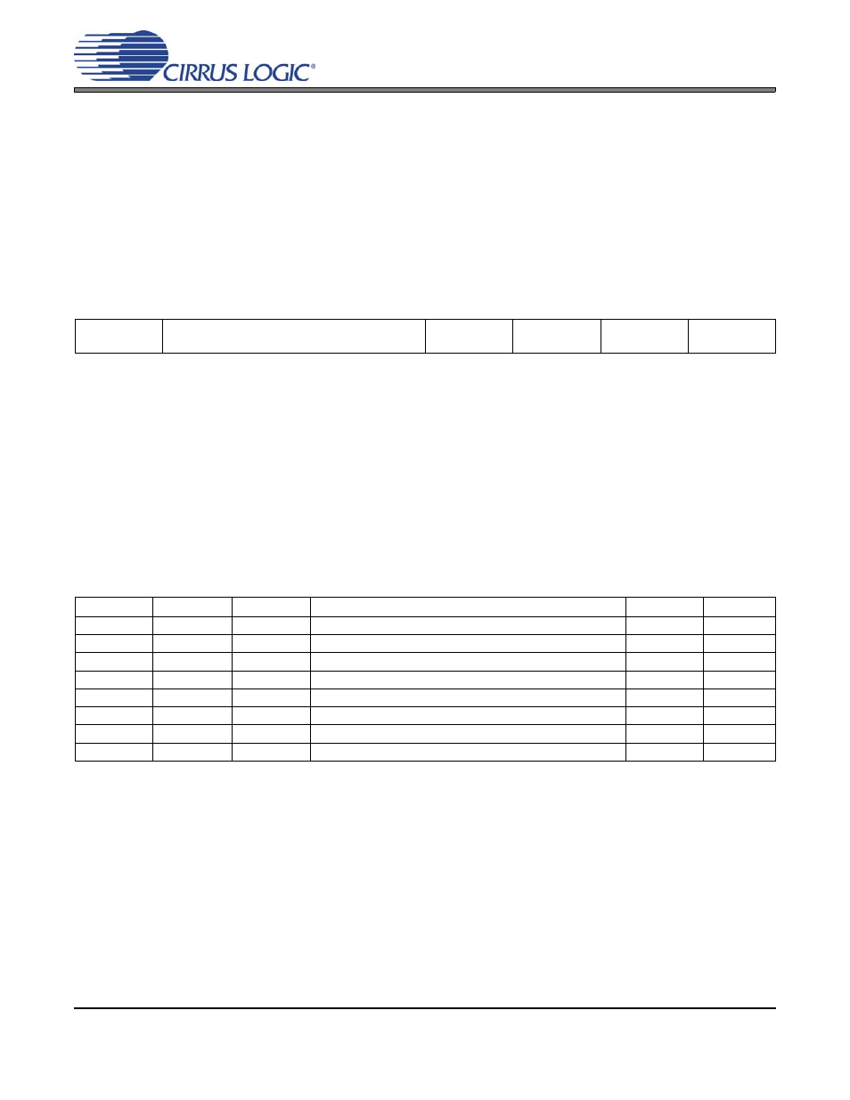
Digital Interface Format (DIF)
Default = 000 - Format 0 (Left Justified, up to 24-bit data)
Function:
These bits select the interface format for the serial audio input. The Functional Mode bits determine
whether PCM or DSD Mode is selected.
PCM Mode: The required relationship between the Left/Right clock, serial clock and serial data is defined
by the Digital Interface Format and the options are detailed in
.
Note:
While in PCM Mode, the DIF bits should only be changed when the power-down (PDN) bit is set
to ensure proper switching from one mode to another.
7
6
5
4
3
2
1
0
Reserved
DIF2
DIF1
DIF0
SDIN4CLK
SDIN3CLK
SDIN2CLK
SDIN1CLK
0
0
0
0
0
0
0
0
DIF2
DIF1
DIF0
DESCRIPTION
Format
FIGURE
0
0
0
Left Justified, up to 24-bit data
0
0
0
1
I²S, up to 24-bit data
1
0
1
0
Right Justified, 16-bit data
2
0
1
1
Right Justified, 24-bit data
3
1
0
0
Right Justified, 20-bit data
4
1
0
1
Right Justified, 18-bit data
5
1
1
0
Reserved
1
1
1
Reserved
Table 1. Digital Interface Formats - PCM Mode