16 control port operation, 1 i²c control, Cs42l73 – Cirrus Logic CS42L73 User Manual
Page 71
DS882F1
71
CS42L73
terrupt Status Register 2 (Address 61h)” on page 123
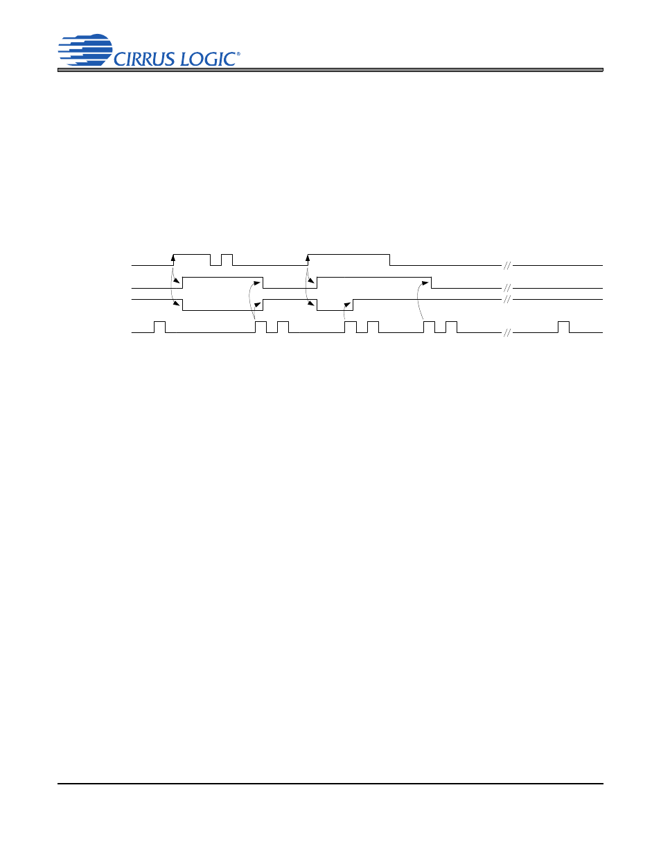
) that are desired to cause an interrupt. The interrupt
pin is either rising-edge or rising-and-falling-edge sensitive to any unmasked interrupt status change event.
It will be set low when any of the unmasked status bits change state in the sensitive direction(s) and it will
remain low until the status register(s) with the interrupt causing bit(s) is (are) read.
Most status bits are “sticky”: If the raw signal feeding the status register bit becomes high, the status register
bit remains high, regardless of the raw signal’s state, at least until the next status register read is completed.
Status bits are implemented as sticky to ensure that transient events are not missed. Reads of the status
register facilitate the clearing of the status bits when the raw signals are no longer high.
With little effort, the present state of a sticky status signals can optionally be determined. Any read indicating
a low level is assured to be the present state. If a high is read, reading the status register again in quick
succession will promptly provide the present, non-sticky state of the status signal.
4.16 Control Port Operation
The control port is used to access the registers allowing the CODEC to be configured for the desired oper-
ational modes and formats. The operation of the control port may be completely asynchronous with respect
to the audio sample rates. However, to avoid potential interference problems, the control port pins must re-
main static if no operation is required.
The control port operates using an I²C interface with the CODEC acting as a slave device. Device commu-
nication must not begin until the reset and power-up timing requirements specified in tables
Specifications—Power, Reset, and Master Clocks” on page 36
and
“Switching Specifications—Control
are satisfied.
Note:
The MCLK signal is not required for I²C communication with the CS42L73. However, an MCLK sig-
nal is required to be present for the programmed registers to take effect; this is because the state
machines affected by register settings cannot be operated without an MCLK signal.
4.16.1 I²C Control
SDA is a bidirectional data line. Data is clocked into and out of the CS42L73 by the clock, SCL. The signal
timings for read and write cycles are shown in
,
, and
. A Start condition is defined as a
falling transition of SDA while the clock is high. A Stop condition is defined as a rising transition of SDA
while the clock is high. All other transitions of SDA occur while the clock is low.
Raw signal feeding
Status Reg. bit
Status Reg. bit
___
INT pin
Register read
signal
Status read value
0
1
1
0
1
0
Read Source
1
0
Poll
c
ycle
Int
e
rru
pt
ser
vi
ce
Ex
tra r
ead fo
r
pr
esent s
ta
te
Int
e
rru
pt
ser
vi
ce
Ex
tra r
ead fo
r
pr
esent s
ta
te
Poll
c
ycle
Ex
tra r
ead fo
r
pr
esent s
ta
te
Poll
c
ycle
Figure 36. Example of Rising-Edge Sensitive, Sticky, Interrupt Status Bit Behavior