2 internal master clock generation, 3 thermal overload notification, Table 1. internal master clock generation – Cirrus Logic CS42L73 User Manual
Page 42: Cs42l73
42
DS882F1
CS42L73
4.2
Internal Master Clock Generation
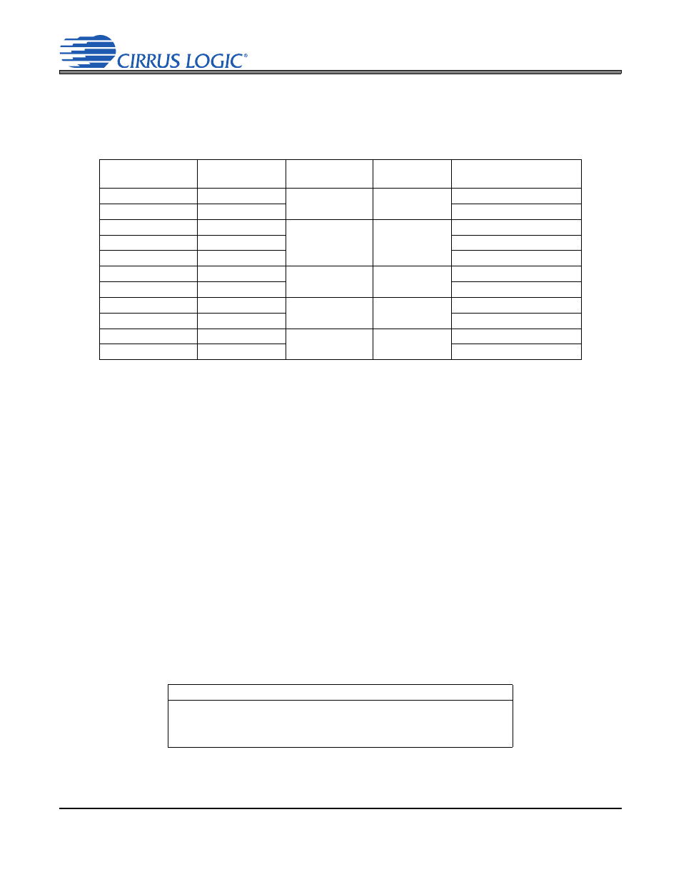
outlines the supported internal Master Clock (MCLK) nominal frequencies and how they are derived
from the supported frequencies of the external MCLK sources (MCLK1 and MCLK2).
4.3
Thermal Overload Notification
The CS42L73 can be configured to notify the system processor when its die temperature is too high. The
processor can use this notification prevent possible damage to the CS42L73 and other devices in the sys-
tem. When notified, the processor should react by powering down CS42L73 (and/or other devices in the
system) partially or entirely, depending on the extent to which the CS42L73’s power dissipation is the cause
of its excessive die temperature. Note, the Speakerphone output, when used, accounts for the vast majority
of the power dissipation from the CS42L73.
To use thermal overload notification:
1. Enable the thermal sense circuitry by programming PDN_THMS.
2. Configure the threshold temperature (via control bits THMOVLD_THLD[1:0]), over which the Thermal
Overload Interrupt Status bit will be set.
3. If an interrupt is desired when the Thermal Overload Detect (THMOVLD) bit toggles from 0b to 1b, set
the M_THMOVLD control to 1b. If polling is desired, set it to 0b.
4. Monitor (read after interrupt or poll) THMOVLD and react accordingly.
Table 1. Internal Master Clock Generation
MCLK1/MCLK2
Rate (MHz)
Required Divide
Ratio
MCLK Rate
(MHz)
Internal Fs
(kHz)
Settings for MCLKDIV[2:0]
5.6448
1
5.6448
44.100
000
11.2896
2
010
6.0000
1
6.0000
46.875
000
12.0000
2
010
24.0000
4
100
6.1440
1
6.1440
48.000
000
12.2880
2
010
13.0000 2
6.5000
50.781
010
26.0000
4
100
19.2000 3
6.4000
50.000
011
38.4000
6
101
Notes:
1.
The MCLKDIV[2:0] register control is described in section
“Master Clock Divide Ratio” on page 87
2.
To save power, MCLK may be disabled using the MCLKDIS register control (refer to section
3.
Refer to section
“SCLK = MCLK Modes” on page 53
for a description of the frequency limitations on
MCLK1 and MCLK2 when using the “SCLK = MCLK” or “SCLK = Pre-MCLK” modes.
Referenced Control
Register Location
PDN_THMS.........................
THMOVLD_THLD[1:0].........
M_THMOVLD ......................
THMOVLD ...........................
“Power Down Thermal Sense” on page 84
“Thermal Overload Threshold Settings” on page 84
“Interrupt Mask Register 1 (Address 5Eh)” on page 122
“Thermal Overload Detect” on page 122