Cirrus Logic CS42L73 User Manual
Cs42l73, Ultralow power mobile audio and telephony codec, Product overview
Copyright
Cirrus Logic, Inc. 2013
(All Rights Reserved)
JULY '13
DS882F1
Ultralow Power Mobile Audio and Telephony CODEC
Product Overview
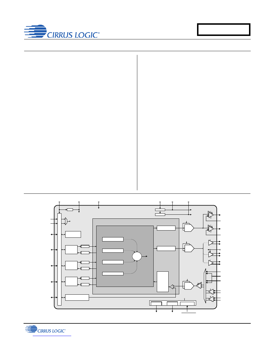
Stereo analog-to-digital converter (ADC)
Dual analog or digital mic support
Dual mic bias generators
Four digital-to-analog converters (DACs)
coupled to five outputs
–
Ground-centered stereo headphone amp.
–
Ground-centered stereo line output
–
Mono ear speaker amplifier
–
Mono 1-W speakerphone amplifier
–
Mono speakerphone line output for stereo
speakerphone expansion
Three serial ports with asynchronous sample
rate converters
Digital audio mixing and routing
Ultralow Power Consumption
3.8-mW quiescent headphone playback
Applications
Smart phones, ultramobile PCs, and mobile
Internet devices
System Features
Native (no PLL required) support for 6/12/
24 MHz, 13/26 MHz, and 19.2/38.4 MHz
master clock rates and typical audio clock rates
Integrated high-efficiency power management
reduces power consumption
–
Internal LDO regulator to reduce internal
digital operating voltage to VL/2 V
–
Step-down charge pump provides low
headphone/line out supply voltage
–
Inverting charge pump accommodates low
system voltage by providing negative rail for
HP and line amplifier
Flexible speakerphone amplifier powering
–
3.00–5.25 V range
–
Independent cycling
Power-down management
–
Individual controls for ADCs, digital mic
interface, mic bias generators, serial ports,
and output amplifiers and associated DACs
Programmable thermal overload notification
High-speed I²C™ control port (400 kHz)
`
Line Outputs
Pseudo Diff. Input
-
+
+VCP_FILT
-VCP_FILT
Digital Processing
Le
ve
l S
h
ift
er
s
CS42L73
Decimator,
HPF,
Noise
Gate,
ALC,
Volume,
Mute,
Swap/Mono
Volume, Mute, Limiter
MCLK
Stereo
Multi-bit
DAC
MCLK
Stereo
Multi-bit
DAC
LDO
VD_FILT
Headphone Outputs
Pseudo Diff. Input
-
+
+VCP_FILT
-VCP_FILT
Ear Speaker Output
VA
-
+
B
Speakerphone Line
Output (Right)
-
+
VP
B
VP
Speakerphone Output
(Left)
-
+
VP
A
VA
VA
Digital MIC Interface
Digital MIC Interface
VL
MCLK
Stereo
Multi-bit
ADC
-6 to +12 dB,
0.5 dB steps
-
+
MIC 2
MIC 1
Pseudo Diff. Input
Pseudo Diff. Input
Line Input (Left)
Line Input (Right)
Pseudo Diff. Input
+10 or
+20 dB
-
+
+10 or
+20 dB
-
+
MIC 1 Bias
MIC 2 Bias
MIC Bias
Short Detect
MIC Bias
Audio Serial Port
Voice Serial Port
Auxiliary Serial Port
Audio
Serial Port
SDOUT
SDIN
ASRC
ASRC
Voice
Serial Port
SDOUT
ASRC
Auxiliary
Serial Port
SDIN
ASRC
SDOUT
ASRC
SDIN
ASRC
-VCP_FILT
Inverting
Step-Down
VCP +VCP_FILT
+VCP_FILT
-VCP_FILT
MCLK
MCLK1
MCLK2
Control Port
Control Port
VP
VD_FILT
Digital Mixer
Volume, Mute, Limiter
MIC2_SDET
+
Audio Serial Port
Voice Serial Port
Auxiliary Serial Port
MIC/Line Input Path
CS42L73
Document Outline
- Table of Contents
- List Of Figures
- List of Tables
- 1. Package Pin/Ball Assignments and Configurations
- 2. Typical Connection Diagram
- 3. Characteristic and Specifications
- Recommended Operating Conditions
- Absolute Maximum Ratings
- DC Electrical Characteristics
- Analog Input To Serial Port Characteristics
- Stereo-ADC and Dual-Digital-Mic Digital Filter Characteristics
- Thermal Overload Detect Characteristics
- ASRC Digital Filter Characteristics
- Mic BIAS Characteristics
- Serial Port to Stereo HP Output Characteristics
- Serial Port to Stereo Line Output Characteristics
- Serial Port to Mono Ear Speaker Output Characteristics
- Serial Port-to-Mono Speakerphone Output Characteristics
- Serial Port to Mono Speakerphone Line Output Characteristics
- Stereo/Mono DAC Interpolation and On-Chip Digital/Analog Filter Characteristics
- Power Consumption
- Digital Interface Specifications and Characteristics
- Switching Specifications—Power, Reset, and Master Clocks
- Switching Specifications—Digital Mic Interface
- Switching Specifications—Serial Ports—I²S Format
- Switching Specifications—Serial Ports—PCM Format
- Switching Specifications—Control Port
- 4. Applications
- 4.1 Overview
- 4.2 Internal Master Clock Generation
- 4.3 Thermal Overload Notification
- 4.4 Pseudodifferential Outputs
- 4.5 Class H Amplifier
- 4.6 DAC Limiter
- 4.7 Analog Output Current Limiter
- 4.8 Serial Ports
- 4.9 Asynchronous Sample Rate Converters (ASRCs)
- 4.10 Input Paths
- 4.11 Digital Mixer
- 4.12 Recommended Operating Procedures
- 4.13 Using MIC2_SDET as Headphone Plug Detect
- 4.14 Headphone Plug Detect and Mic Short Detect
- 4.15 Interrupts
- 4.16 Control Port Operation
- 4.17 Fast Start Mode
- 4.18 Headphone High-Impedance Mode
- 5. Register Quick Reference
- 6. Register Description
- 6.1 Fast Mode Enable (Address 00h)
- 6.2 Device ID A and B (Address 01h), C and D (Address 02h), and E (Address 03h) (Read Only)
- 6.3 Revision ID (Address 05h) (Read Only)
- 6.4 Power Control 1 (Address 06h)
- 6.5 Power Control 2 (Address 07h)
- 6.6 Power Control 3 and Thermal Overload Threshold Control (Address 08h)
- 6.7 Charge Pump Frequency and Class H Configuration (Address 09h)
- 6.8 Output Load, Mic Bias, and MIC2 Short Detect Configuration (Address 0Ah)
- 6.9 Digital Mic and Master Clock Control (Address 0Bh)
- 6.10 XSP Control (Address 0Ch)
- 6.11 XSP Master Mode Clocking Control (Address 0Dh)
- 6.12 ASP Control (Address 0Eh)
- 6.13 ASP Master Mode Clocking Control (Address 0Fh)
- 6.14 VSP Control (Address 10h)
- 6.15 VSP Master Mode Clocking Control (Address 11h)
- 6.16 VSP and XSP Sample Rate (Address 12h)
- 6.17 Miscellaneous Input and Output Path Control (Address 13h)
- 6.18 ADC/Input Path Control (Address 14h)
- 6.19 Mic PreAmp and PGA Volume Control: Channel A (Mic 1, Address 15h) and Channel B (Mic 2, Address 16h)
- 6.20 Input Path x Digital Volume Control: Channel A (Address 17h) and B (Address 18h)
- 6.21 Playback Digital Control (Address 19h)
- 6.21.1 Speakerphone [A], Ear Speaker/Speakerphone Line Output [B] (SES) Playback Channels B=A
- 6.21.2 Headphone/Line Output (HL) Playback Channels B=A
- 6.21.3 Limiter Soft-Ramp Disable
- 6.21.4 Ear Speaker/Speakerphone Line Output Digital Mute
- 6.21.5 Speakerphone Digital Mute
- 6.21.6 Headphone/Line Output (HL) x Digital Mute
- 6.22 Headphone/Line Output (HL) x Digital Volume Control: Channel A (Address 1Ah) and B (Address 1Bh)
- 6.23 Speakerphone Out [A] Digital Volume Control (Address 1Ch)
- 6.24 Ear Speaker/Speakerphone Line Output (ESL) [B] Digital Volume Control (Address 1Dh)
- 6.25 Headphone Analog Volume Control: Channel A (Address 1Eh) and B (Address 1Fh)
- 6.26 Line Output Analog Volume Control: Channel A (Address 20h) and B (Address 21h)
- 6.27 Stereo Input Path Advisory Volume (Address 22h)
- 6.28 XSP Input Advisory Volume (Address 23h)
- 6.29 ASP Input Advisory Volume (Address 24h)
- 6.30 VSP Input Advisory Volume (Address 25h)
- 6.31 Limiter Attack Rate Headphone/Line Output (HL) (Address 26h)
- 6.32 Limiter Control, Release Rate Headphone/Line Output (HL) (Address 27h)
- 6.33 Limiter Min/Max Thresholds Headphone/Line Output (HL) (Address 28h)
- 6.34 Limiter Attack Rate Speakerphone [A] (Address 29h)
- 6.35 Limiter Control, Release Rate Speakerphone [A] (Address 2Ah)
- 6.36 Limiter Min/Max Thresholds Speakerphone [A] (Address 2Bh)
- 6.37 Limiter Attack Rate Ear Speaker/Speakerphone Line Output (ESL) [B]
- 6.38 Limiter Control, Release Rate Ear Speaker/Speakerphone Line Output (ESL) [B] (Address 2Dh)
- 6.39 Limiter Min/Max Thresholds Ear Speaker/Speakerphone Line Output (ESL) [B]
- 6.40 ALC Enable and Attack Rate AB (Address 2Fh)
- 6.41 ALC Release Rate AB (Address 30h)
- 6.42 ALC Threshold AB (Address 31h)
- 6.43 Noise Gate Control AB (Address 32h)
- 6.44 ALC and Noise Gate Misc Control (Address 33h)
- 6.45 Mixer Control (Address 34h)
- 6.46 Stereo Mixer Input Attenuation (Addresses 35h through 54h)
- 6.47 Mono Mixer Controls (Address 55h)
- 6.48 Mono Mixer Input Attenuation (Addresses 56h through 5Dh)
- 6.49 Interrupt Mask Register 1 (Address 5Eh)
- 6.50 Interrupt Mask Register 2 (Address 5Fh)
- 6.51 Interrupt Status Register 1 (Address 60h)
- 6.52 Interrupt Status Register 2 (Address 61h)
- 6.53 Fast Mode 1 (Address 7Eh)
- 6.54 Fast Mode 2 (Address 7Fh)
- 7. PCB Layout Considerations
- 8. Performance Data
- 9. Parameter Definitions
- 10. Package Dimensions
- 11. Thermal Characteristics
- 12. Ordering Information
- 13. References
- 14. Revision History