Cirrus Logic CS4224 User Manual
Bit 105 db audio codec with volume control, Features, Description
This manual is related to the following products:
Table of contents
Document Outline
- CS4223 CS4224
- Features
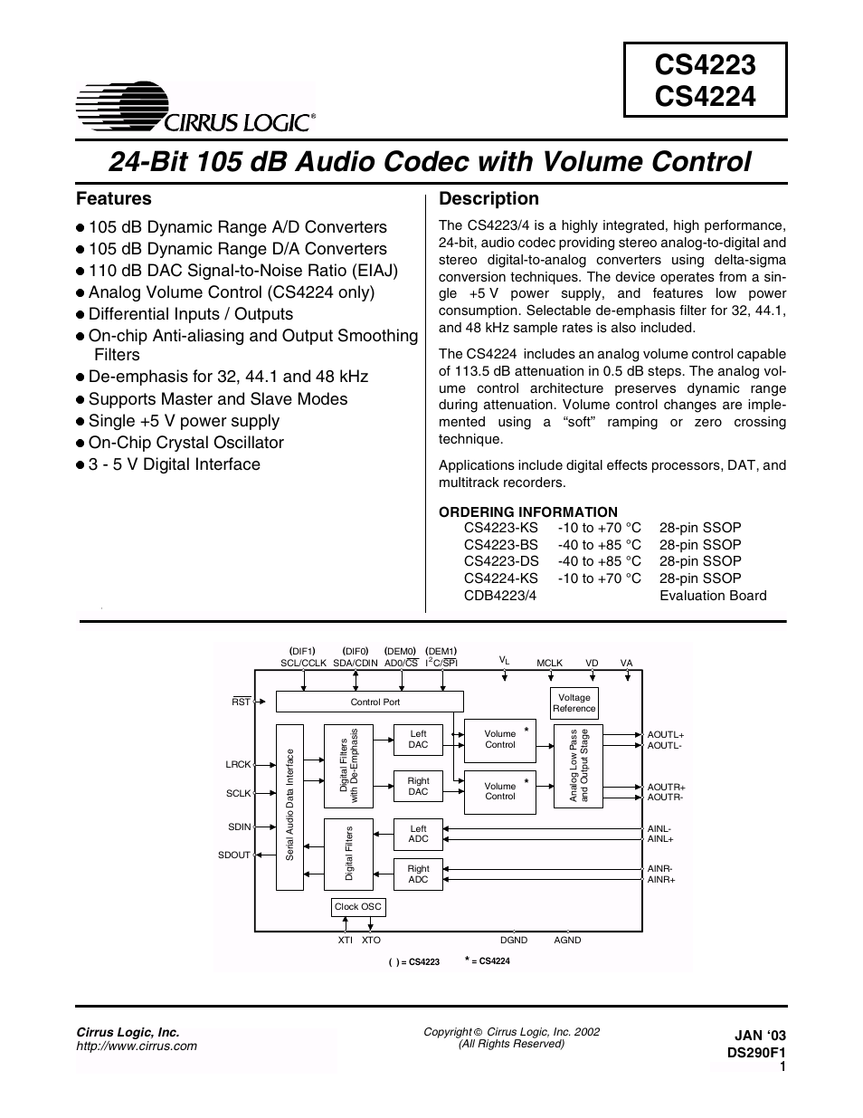
- Description
- Table of Contents
- List of Figures
- List of Tables
- 1. Characteristics and Specifications
- 2. Typical Connection Diagram — CS4223
- 3. Typical Connection Diagram — CS4224
- 4. Register Quick Reference - CS4224
- 5. Register Descriptions - CS4224
- 5.1.1 Power Down ADC (PDN)
- 5.1.2 Left and Right channel High Pass Filter Defeat (HPDR-HPDL)
- 5.1.3 Left and Right Channel ADC Muting (ADMR-ADML)
- 5.1.4 Calibration Control (CAL)
- 5.1.5 Calibration Status (CALP) (Read Only)
- 5.1.6 Clocking Error (CLKE) (Read Only)
- 5.2.1 Mute on Consecutive Zeros (MUTC)
- 5.2.2 Mute Control (MUTR-MUTL)
- 5.2.3 Soft RAMP Control (SOFT)
- 5.2.4 Soft RAMP Step Rate (RMP)
- 5.4.1 Attenuation level (ATT7-ATT0)
- Table 1. Example Volume Settings
- 5.5.1 De-emphasis Control (DEM)
- 5.5.2 Serial Input/Output Data SCLK Polarity Select (DSCK)
- 5.5.3 Serial Data Output Format (DOF)
- 5.5.4 Serial Data Input Format (DIF)
- 5.6.1 Left and Right Channel Acceptance Bit (ACCR-ACCL)
- 5.6.2 Left and Right Channel ADC Output Level (LVR and LVL)
- 5.7.1 Master Clock Control (MCK)
- 6. Pin Descriptions — CS4223
- 7. Pin Descriptions — CS4224
- 8. Applications
- 8.1 Overview
- 8.2 Grounding and Power Supply Decoupling
- 8.3 High Pass Filter
- 8.4 Analog Outputs
- 8.5 Master vs. Slave Mode
- 8.6 De-emphasis
- 8.7 Power-up / Reset / Power Down Calibration
- 8.8 Control Port Interface (CS4224 only)
- 8.8.1 SPI Mode
- 8.8.2 I2C Mode
- 8.9.1 Auto-Increment Control (INCR)
- 8.9.2 Register Pointer (MAP)
- Figure 6. Control Port Timing, SPI mode
- Figure 7. Control Port Timing, I2C mode
- Figure 8. Serial Audio Format 0 (I2S)
- Figure 9. Serial Audio Format 1
- Figure 10. Serial Audio Format 2
- Figure 11. Serial Audio Format 3
- Figure 12. Optional Input Buffer
- Figure 13. Single-ended Input Application
- Figure 14. 2- and 3-Pole Butterworth Filters
- Figure 15. De-emphasis Curve
- Figure 16. Hybrid Analog/Digital Attenuation
- 9. ADC/DAC Filter Response
- 10. Parameter Definitions
- 11. Package Dimensions