Design and function – WIKA TR75 User Manual
Page 10
11325232.04 01/2014 GB/D/F/E
10
WIKA operating instructions DiwiTherm
®
, model TR75
GB
The sensor diameter should be approx. 1 mm smaller than the bore diameter of the
thermowell or the blind bore, respectively.
Gaps of more than 0.5 mm between thermowell and the sensor will have a negative effect on
the heat transfer, and they will result in unfavourable response behaviour of the thermometer.
Sensor lengths
Sensor Ø in mm
Standard sensor lengths A (l
1
) in mm
6
50
100
150
8
-
100
150
Special lengths are possible.
Process connection
A compression fitting enables simple, on-site adjustment to the required insertion length.
Compression fitting
Material: stainless steel
G ¼ B male thread (not with Ø 8 mm sensors) or G ½ B
Delivery also possible without process connection.
Cable
Silicone, shielded, application range -40 ... +200 °C with EMC cable gland
Cable length to customer specification.
The sensor sleeve and case are connected by the cable shielding. Earthing on both ends
can lead to potential losses and indication inaccuracy.
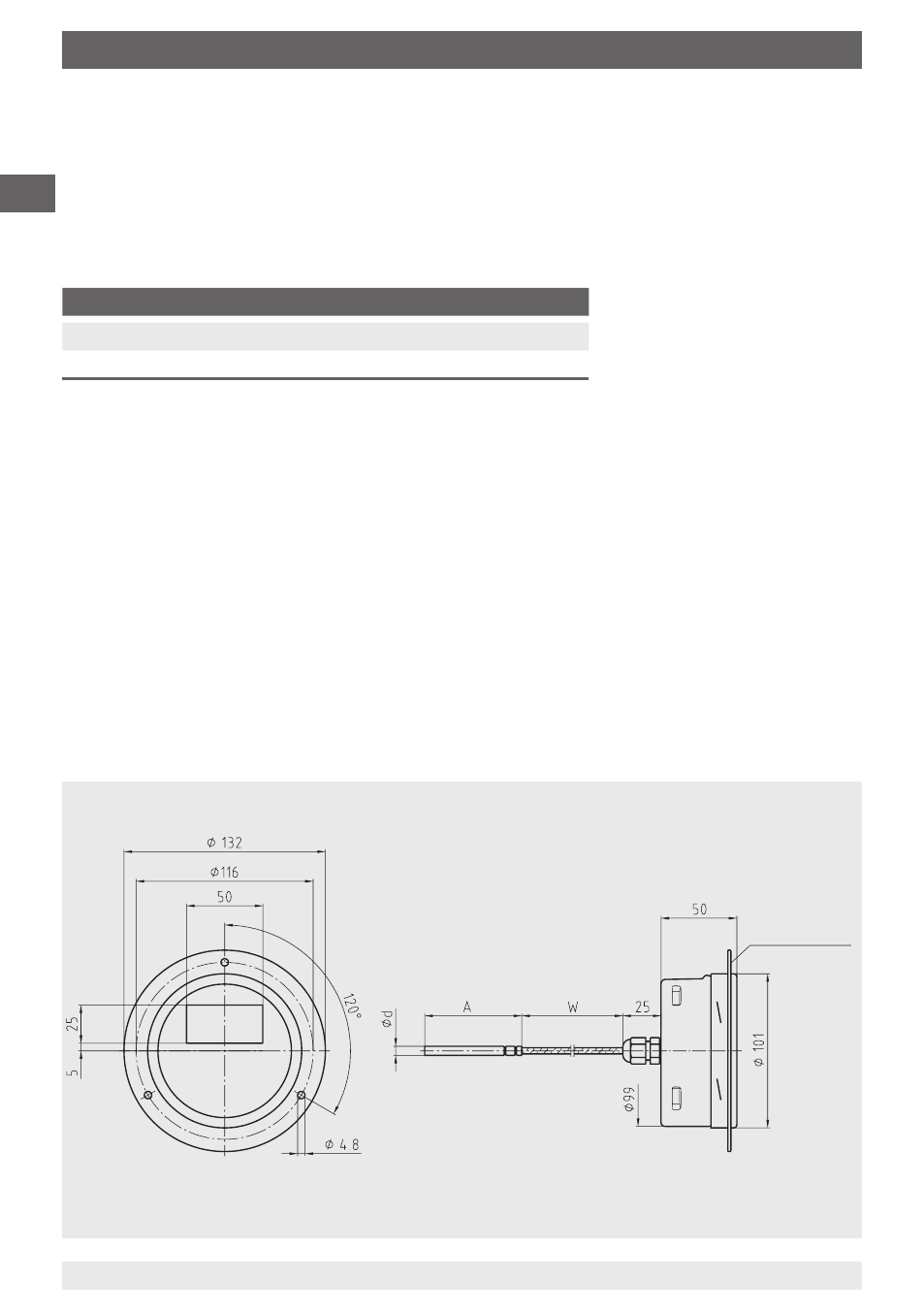
3165575.05
Panel mounting
flange
DiwiTherm
®
battery operation, model TR75 with sensor for insertion, rear cable entry, with
panel mounting flange
Legend:
Ø d Sensor diameter
A
Insertion length
W
Cable length
4. Design and function