Technical data – WIKA PGT43.100 User Manual
Page 5
GB
11
97
64 05/
009 GB/D/F/E
WIKA Operating Instructions intelliGAUGE family
5
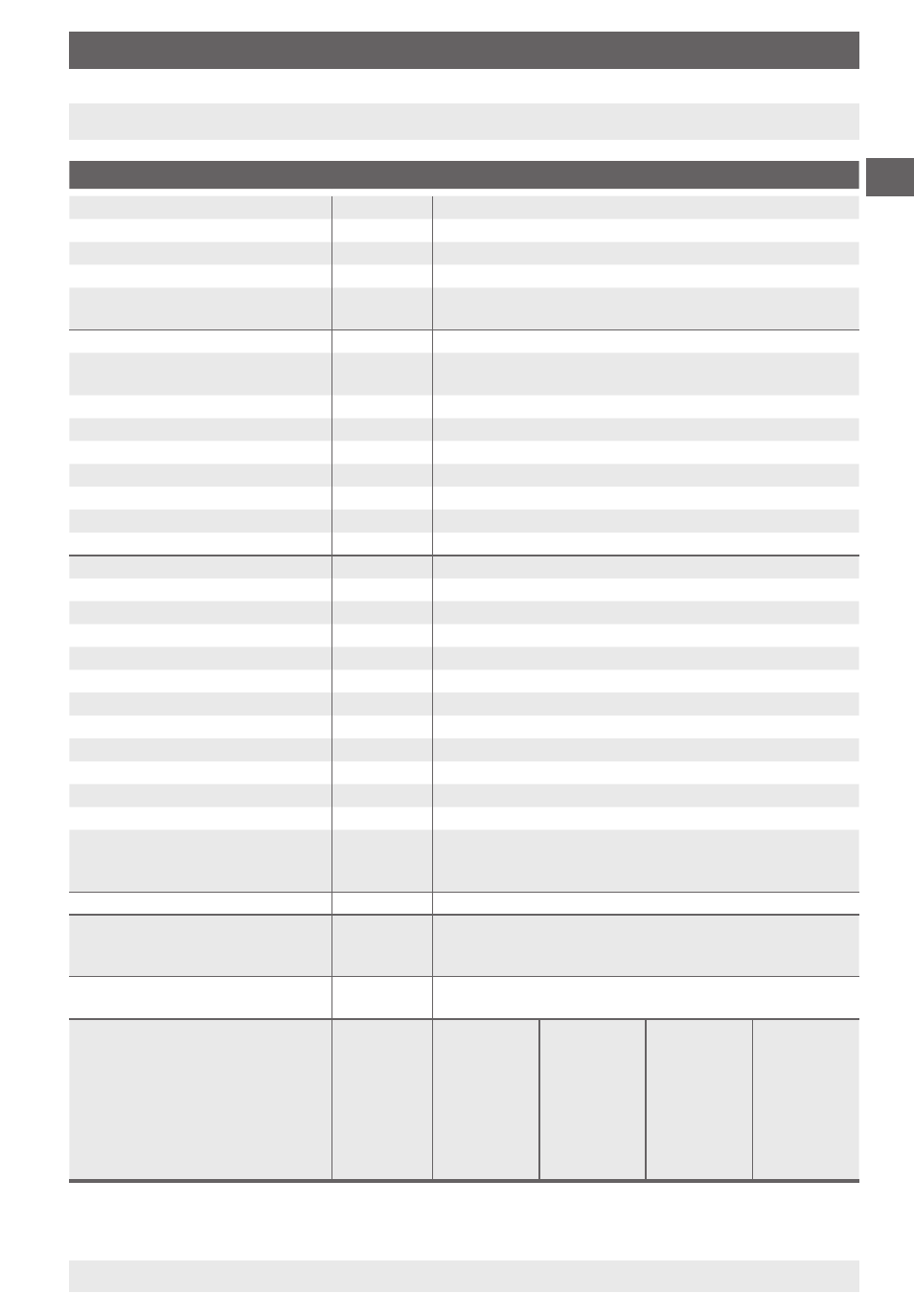
3.1 Transmitter
1)
Power supply UB
DC V
1
≤ UB ≤ 30≤
Supply voltage effect
% of FS/10 V
≤ 0.1
Permissible residual ripple
% ss
≤ 10
Output signal, variant I
4 … 0 mA, -wire, passive, per NAMUR NE4
Permissible max. load RA
RA ≤ (UB - 1 V)/0.0 A with RA in Ohm and UB in Volt
however max. 600
Ω
Effect of load
% FS
≤ 0.1
Output signal, variant II
4 … 20 mA, 2-wire - Ex≤, per ATEX Ex II 2G Ex ia IIC T4/T5/
T6 or Ex I M Ex ia I
Output signal, variant III
0 ... 0 mA, -wire
)
Output signal, variant IV
0 ... 10 V *
Impendance on the voltage output
Ω
0.5
Load-carrying ability voltage output
k
Ω
… 100
Sample rate sensor
ms
600, with -wire optionally faster
Electrical zero point
Zeroing through short-term jumper across ternimals 5 and 6
Zero point adustable range
< °
45
Linearity
% of span
≤ 1.0 (limit point calibration)
Output signal accuracy
% FS
0. (only electronic)
Resolution
% FS
0.15 (10 bit resolution at 60°)
Update rate (measuring rate)
1/s
> 1
Input signal rotational angle
< °
0 … 70
Expanded special span
< °
< 0 (Option)
Long-term stability of electronics
% FS/a
< 0.
Temperature error, electronics
% FS/10K
< 0. (over the complete temperature range)
Warming-up time
min.
≤ 5
Permissible ambient temperature
°C
-40 … +60
Permissible storage temperature
°C
-40 … +70
Permissible medium temperature
°C
-40 … +100
Special function
Option: non-proportional angular output signal, via auxili-
ary points and interpolation of the intermediate values (to
specify with the order)
CE-conformity
Interference emission and immunity per EN 61 6-1
Wiring
L-plug connector, 180 °C rotatable, max. 1.5 mm², wire
protector, Cable gland M0 x 1.5, External cable diameter
7-1 mm, incl. strain relief
Wiring protection
IP65 to EN 60 59 / IEC 59;
Protected against reverse polarity and overvoltage
Connection details,
depending on variant
Terminal
No
1
4
5
6
Variant I
4 ... 0mA
GND
I+
reserved
reserved
Zeroing
Zeroing
Ex-Variant II
4 ... 0mA
GND
I+
reserved
reserved
Zeroing
Zeroing
Variant III
0 ... 0 mA
GND
UB+
Iout
reserved
Zeroing
Zeroing
Variant IV
0 ... 10V
GND
UB+
Uout
reserved
Zeroing
Zeroing
1) Not model PGT.06
) Not model DPGT4HP.100 / DPGT4HP.160
)
)
3. Technical data
)
3. Technical data