Installation and commissioning – WIKA PGT43.100 User Manual
Page 12
GB
4. Installation instructions / 5. Installation and commissioning
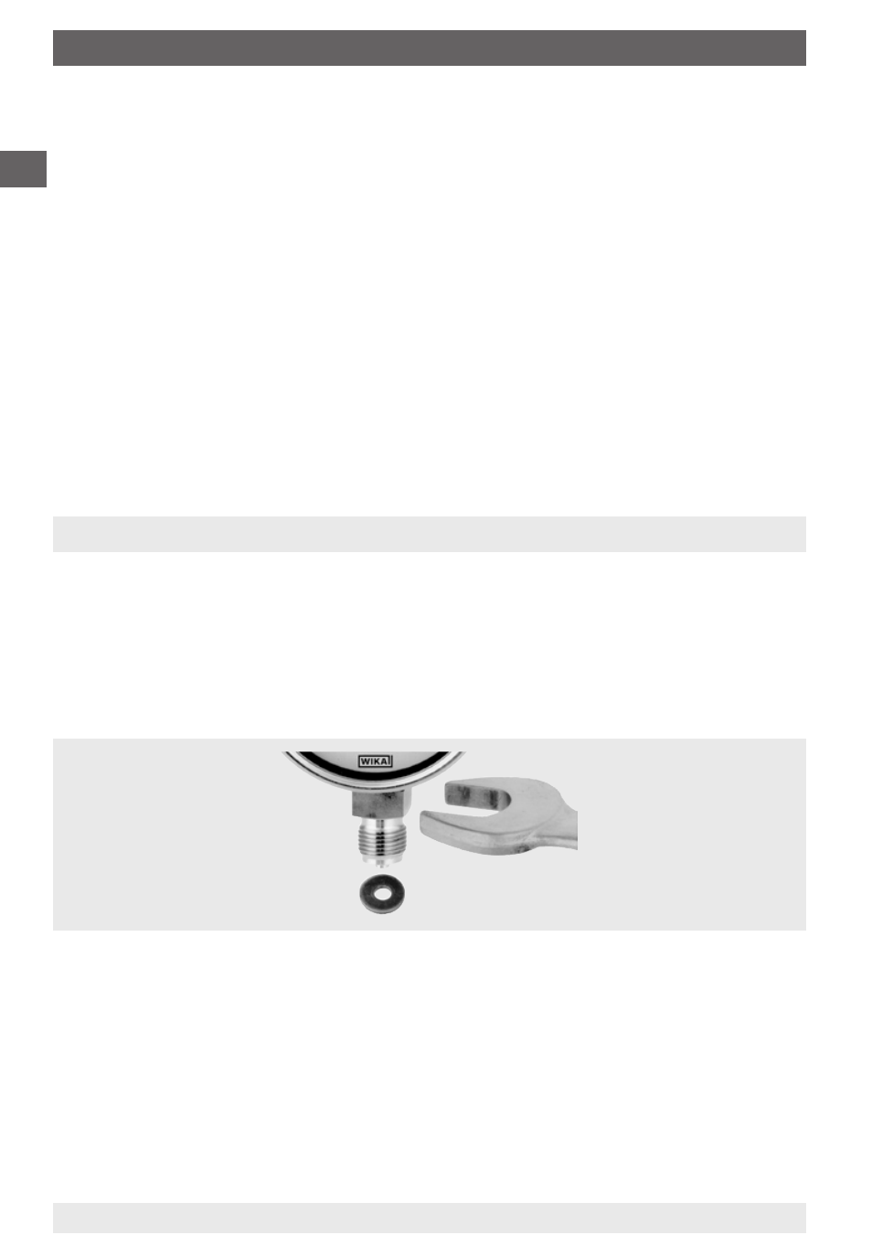
Installation using
a spanner
11
97
64 05/
009 GB/D/F/E
WIKA Operating Instructions intelliGAUGE family
1
Pressure test connection
The pressure test connection, with a sufficiently large bore (
≥ 6 mm diameter),
should be arranged, as far as possible, over a shut-off device, in a position
where the accuracy of the reading will not be affected by the flow of the media
being measured.
The piping between the pressure test connection and the pressure instrument
should have an inner diameter large enough to avoid blockages or delays in
pressure transmission. Also, it should not have any sharp bends. It is recom-
mended that it is mounted with a continuous incline of approx. 1:15.
Piping
The piping should be arranged and fitted so that it can withstand the stresses
caused by expansion, vibration and the influence of heat. When the media is
gaseous, a water drain point should be provided at the lowest point. For liquid
pressure media, an air bleed should be provided at the highest point.
5. Installation and commissioning
The correct sealing of pressure connections should be achieved by means of
suitable sealing rings, sealing washers or WIKA profile seals.
We recommend connection by means of a union nut or a LH-RH adjusting nut
in order to simplify correct orientation of the gauge. When mounting them or
removing them, the pressure gauges must not be tightened using the housing,
but only on the spanner flats on the stem!
If the pressure transmitter is positioned lower than the pressure test connec-
tion, the tailpipe should be thoroughly cleaned prior to fitting the transmitter.
For technical reasons, it is necessary to ventilate liquid-filled pressure gauges
after installation. See the relevant label on the pressure gauge.