Maintenance, accessories, Trouble shooting – WIKA WU-16 User Manual
Page 9
2460160.06 GB/D/F/E 01/2010
16 WIKA Operating instructions/Betriebsanleitung/Mode d'emploi/Instrucciones de servicio WU-1X
2460160.06 GB/D/F/E 01/2010
17
WIKA Operating instructions/Betriebsanleitung/Mode d'emploi/Instrucciones de servicio WU-1X
Failure
Possible cause
Procedure
Output signal unchanged after change
in pressure
Mechanical overload through over-
pressure
Replace instrument; if failure reoccurs,
consult the manufacturer *)
Wrong supply voltage or current spike Replace instrument
No output signal
No/incorrect voltage supply or current
spike
Adjust the voltage supply to correspond
with the Operating Instructions *)
Cable break
Check connections and cable
No/False output signal
Incorrectly wired (e.g. Connected as
2-wire instead of 3-wire system)
Follow pin assignment (see Instrument
Label / Operating Instructions)
Abnormal output signal or
Abnormal zero point signal
Zero point set wrongly
Adjust zero point correctly (see chapter
8); a sufficiently accurate current/volt
meter should be used
9. Maintenance, accessories
WIKA transducers require no maintenance.
Have repairs performed by the manufacturer only.
9. Maintenance, accessories
GB
Board Replacement
For board replacement, vent the transducer to pressureless state.
Remove all power to the transducer.
Protect the transducer from voltage, or static discharge, to prevent possible damage.
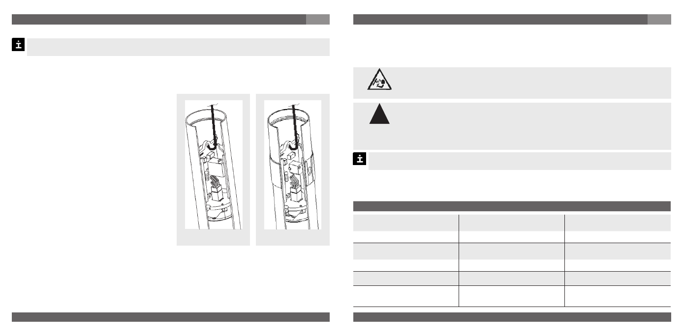
Disassembly
1. Protect the PCB and other electrical
devices from voltage, or static discharge,
to prevent possible damage. Ensure you
have a ground strap attached to your body.
2. Remove the locking ring, on the top of
transducer.
3. Carefully pull the assembly out of the
transducer housing, as far as the internal
con-nector cable will allow. Remove the
4-pin connector from the universal
electron-ics board assembly.
4. Hang the tool supplied with the replacement
PCB into the bore of the PCB.
5. While firmly holding the transducer body,
pull the PCB straight out of the
transducer body assembly.
Reassembly
1. Firmly push the new PCB into the transducer body as far as it will go.
2. Align the pins on the connector from the electrical connector with the sockets on the new
universal electronics board assembly.
3. Rotate the electrical connector on the transducer housing to the keyed insertion.
Replace and hand tighten the locking ring, on the top of transducer.
without side-access
with side-access
9. Maintenance, accessories / 10. Trouble shooting
GB
Accessories: For details about the accessories (e. g. connectors), please refer to WIKA‘s
price list, WIKA‘s product catalog on CD or or contact our sales department.
10. Trouble shooting
Open pressure connections only after the system is without pressure!
Do not insert any pointed or hard objects into the pressure port for cleaning to prevent
damage to the diaphragm of the pressure connection.
Take precautions with regard to remaining media in removed transducers.
Remaining media in the pressure port may be hazardous or toxic!
Remove the transducer from service and mark it to prevent it from being
used again accidentally, if it becomes damaged or unsafe for operation.
Have repairs performed by the manufacturer only.
Please verify in advance if pressure is being applied (valves/ ball valve etc. open) and if the
right voltage supply and the right type of wiring (2-wire/3-wire) has been chosen?
Warning
!
Warning