WIKA WU-16 User Manual
Page 8
2460160.06 GB/D/F/E 01/2010
14 WIKA Operating instructions/Betriebsanleitung/Mode d'emploi/Instrucciones de servicio WU-1X
2460160.06 GB/D/F/E 01/2010
15
WIKA Operating instructions/Betriebsanleitung/Mode d'emploi/Instrucciones de servicio WU-1X
When designing your plant, take into account that the stated values (e.g.burst pressure,
over pressure safety) apply depending on the material, thread and sealing element used.
7. Starting, operation / 8. Adjustment of zero point
GB
Functional test
Open pressure connections only after the system is without pressure!
Observe the ambient and working conditions outlined in section 7
„Technical data.
Please make sure that the transducer is only used within the over load
threshold limit at all times!
When touching the transducer, keep in mind that the surfaces of the instru-
ment components might get hot during operation.
The output signal must be proportional to the pressure. If not, this might point to a
damage of the diaphragm. In that case refer to chapter 10 „Troubleshooting“.
8. Adjustment of zero point
GB
8. Adjustment of zero point
These Transducers are maintenance free.
If a zero offset occurs anyhow, this can be adjusted by means of a built-in potentiometer.
For verification and adjustment of the zero point, vent the transducer to zero (0)PSI for gage
reference transducers. The potentiometer for the zero adjustment is protected inside the trans-
ducer housing. Use a 0.040" to 0.060" (1 to 1.5 mm) jeweler's screwdriver for adjustment.
Span adjustment is not necessary after zero point correction.
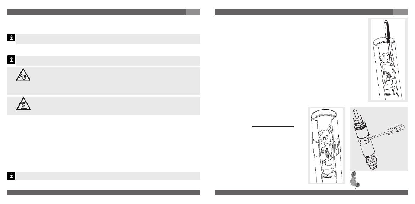
Procedure for Transducer without Side-Access
1. Remove all power to the transducer.
2. Remove the locking ring, on the top of transducer, in order to expose
the zero adjusting potentiometer. Carefully pull the assembly out of the
transducer housing, as far as the internal connector cable will allow.
3. Restore power to the transducer.
4. Vent the transducer to pressureless state. Monitor the output signal,
and adjust the zero screw to 4mA or 0.1V depending on the signal
output. The Zero adjustment screws are both turned in a clockwise
direction to increase the signal or in a counter clock-wise direction to
decrease the signal.
5. Remove all power to the transducer again.
6. Rotate the electrical connector on the transducer housing to
the keyed insertion. After this, replace and hand tighten the
locking ring on the top of transducer.
For version FM-Approved please note the special connection conditions on the enclosed
control drawing.
Procedure for Transducer with Side-Access
1. Turn the grip ring until the access to the
potentiometer is free.
2. Adjust the zero point by means of the
potentiometer in pressureless state.
When doing this, do not contact other
components with the screw driver to
excluse a short circuit in the instrument.
Check the zero point by means of a
suitable instrument. Clockwise rotation
means an upward zero offset,
anti-clockwise rotation means a down
ward zero offset.
3. After this, turn the grip screw until the
access to the potentiometer is closed
again.
For further information
(+49) 9372/132-295
Warning
Caution