Typical wiring diagram, Locating system distance – Light Engineered Displays Linear Detection with Footage Marks User Manual
Page 2
DL
SERIES
LOCATING SYSTEM
DISTANCE
4“ SQUARE BOX
Main input power must be from appropriate
disconnect device, as per code require-
ments.
Wiring must be routed and supported in
manner that prevents strain or damage to
wire and connectors.
Conduit provides grounding.
1.
2.
3.
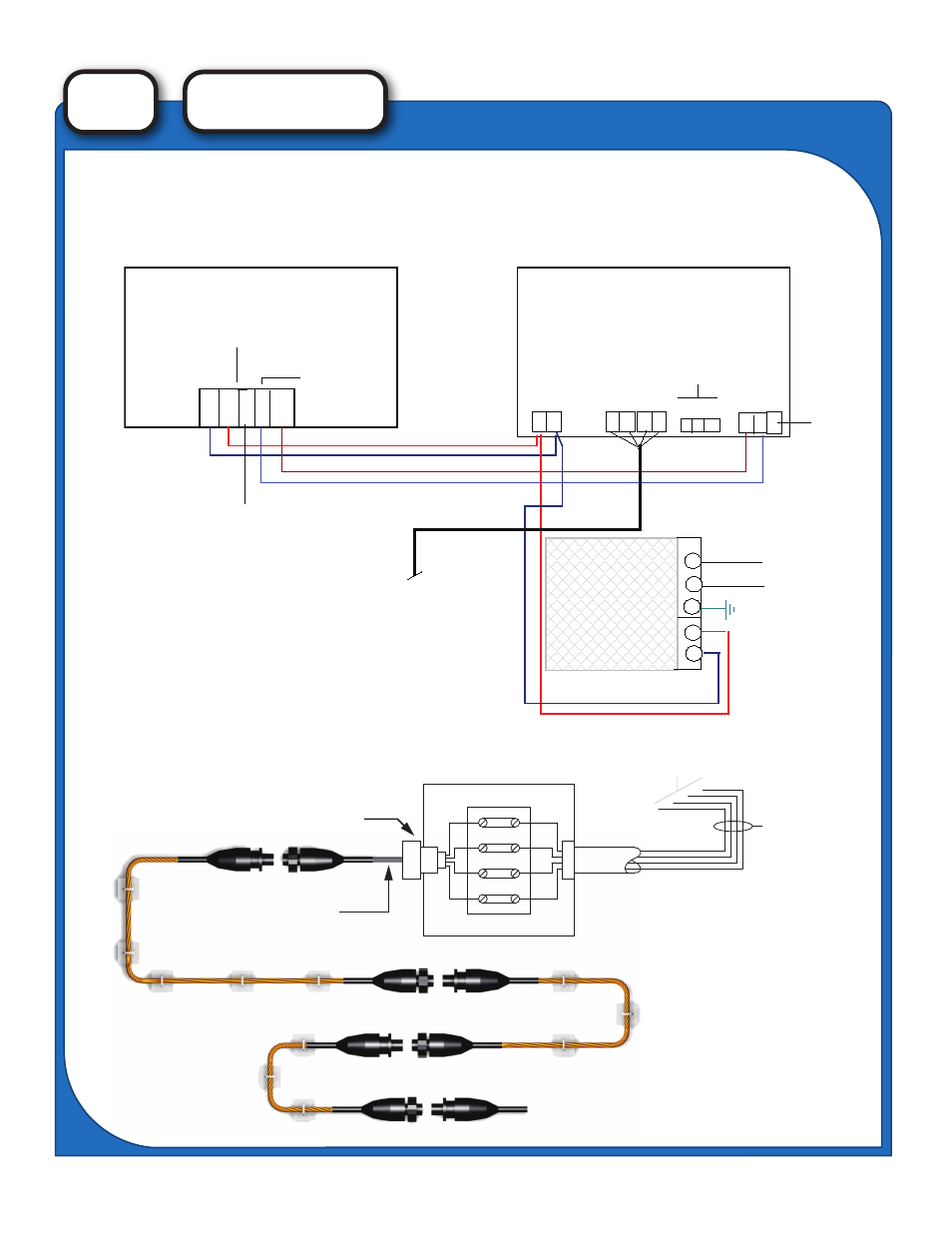
Typical Wiring Diagram
LCD-240
LD-2000
1 2 3 4 5
Pwr
Data
+
-
RX +
RX -
Pwr
+ -
W BG R
To Water Leak Sensing Cable
Power Supply
Display on Door
Controller in Backbox
A B S
+ -
n/c
n/c
120 vac input
24 vdc output
H
N CAUTION
120 VAC
Rear View
NO C NC
Contacts
END OF LINE DEVICE
18 Gauge THHN
four-conductor cable
with jacket. Install
per local codes.
CONDUIT
STARTER CABLE
DLC-100
DLC-50
STRAINRELIEF
WITH RUBBER BUSHING
CONNECTORS
NOTE: CABLE LENGTH SHOULD BE LIMITED
TO 1400 FEET PER ZONE, MAXIMUM.
NOTE: If the start of the DLC-100 cable is
within 10’ of the controller, the starter
cable can be connected directly to the
controller.
TO CONTROLLER
- LD Series (1 page)
- LD Series (2 pages)
- LD Series ANNUNCIATORS GRAPHIC (2 pages)
- Switch and Lock Specifications (1 page)
- BA Series (1 page)
- EM Series (2 pages)
- LD Series DIRECTORY ANNUNCIATORS (2 pages)
- SP Series LIGHTED STATUS PANELS (2 pages)
- DA Series GANG MOUNTED DIRECTORY (2 pages)
- MNS Series LEDARRAY INDOOR DISPLAY (6 pages)
- MNS Series MEGADOT INDOOR DISPLAY (2 pages)
- MNS Series SP-2/MNS LIGHTED PANELS (2 pages)
- WT Series (2 pages)
- SS Series (2 pages)
- FS Series FAN STATUS & CONTROL (2 pages)
- FS Series PURGE PANEL CONTROLLER (2 pages)
- LCD-240 Alpha/Numeric Display (2 pages)
- LCD-240G Graphic Map w/ Display (2 pages)
- LI Loop Converter Interface (2 pages)
- VDT Serial Data Annunciator (1 page)
- Dot Matrix Printers (1 page)
- ARA 911 Phone (2 pages)
- ARA Panel w/no Intercom (ST) (2 pages)
- Call Station (ST) (1 page)
- SP-1/ARA Lighted Panels (1 page)
- WD-SD Series - Spot Detector (2 pages)
- WD-SD Series - Wiring Diagram (1 page)
- WD-1 Control Panel (2 pages)
- Linear Detection with Graphics (2 pages)
- Leak Detector Cable WDC-100 (2 pages)
- Section 16500 Specs (2 pages)
- DLC Series - Leak Detection Cable (2 pages)
- AquaAlert Installation Guide (2 pages)
- AquaAlert Technical Specifications (2 pages)
- Fuel Leak Control Panel (2 pages)
- Linear Fuel Leak Sensor (1 page)
- Dual Liquid Sensors (1 page)
- Temperature and Humidity Sensors (2 pages)
- Liquid Level Detection Float Switch (1 page)
- Liquid Level Detection Tetherswitch (2 pages)
- Pull Station Covers (1 page)
- Smoke Detector Covers (1 page)
- Keypad and Thermostat Covers (1 page)