Light Engineered Displays WD-SD Series - Wiring Diagram User Manual
Wd-sd 0v, Wd-sd/12 or wd-sd/24, Wd-sd
A Division of:
Light Engineered Displays, Inc.
109 Portwatch Way
Wilmington, N.C. 28412
Phone: (800) 251-2512
Fax: (800) 251-9878
Internet: www.ledinc.com
Email: [email protected]
WD-SD
SERIES
SPOT DETECTION
WIRING DIAGRAM
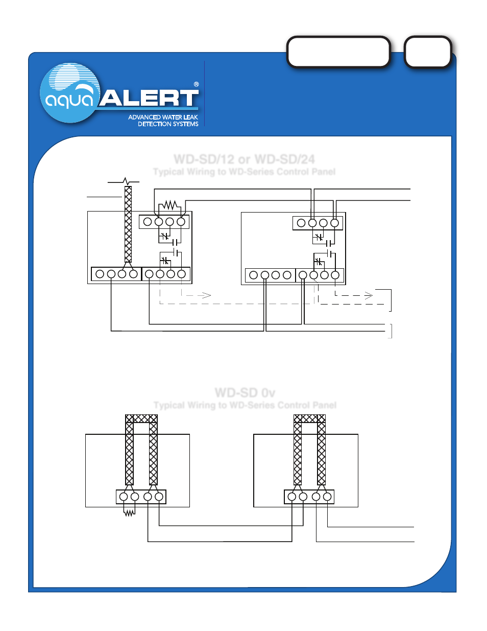
WD-SD 0v
Typical Wiring to WD-Series Control Panel
NOTE: The WD-SD 12 or 24v Spot Detector is also compatible with all 12 or 24 vdc alarm systems.
To supervise the power connections, use a normally energized relay at the end of the line, and
put the EOL resistor in series with the closed contact.
First Detector
Last Detector
WD-SD 0v
WD-SD 0v
15K EOL
6" of sensor cable is included
Optional connections to
Remote Graphic Annunciator
12 or 24 volt DC Power Input, based on model
To Input Zone of WD-1 or WD-4
NOTE: The WD-SD 0v Spot Detector is compatible ONLY with AquaALERT Leak Detection Systems.
The sensor cable and wiring is full supervised by the AquaALERT EM-1 or EM-4 control card of the WD-Series system.
For specific applications, please consult the factory.
WD-SD/12 or WD-SD/24
Typical Wiring to WD-Series Control Panel
-
Sensor
+
-
+
R.G.A
To Alarm Panel Zone Input
WD-1, WD-4, OR OTHER
ALARM CONTROL PANEL
E.O.L RESISTOR AS REQUIRED
N/C
N/C
LAST DETECTOR
TB-1
TB-2
DPDT CONTACTS @ 1 AMP