Architect / engineer specification, Technical specifications – Light Engineered Displays Linear Detection with Graphics User Manual
Page 2
LW
SERIES
GRAPHIC SYSTEM
WATER DETECTION
Architect / Engineer Specification
The contractor shall provide a combination zone water detection system and graphic annunciator display panel. The
system shall be as manufactured by AquaALERT, a division of Light Engineered Displays, Inc, or equal. Spot detectors
and footage measuring systems are not acceptable. System will be U.L. Listed.
An audible alarm shall be provided for indication of water detection alarm and shall be equipped with a silence feature. The
system shall provide for subsequent audible alarm for each zone. The zones shall supervise the water sensing conductors
for continuity. Pulsed AC supervision shall be utilized to minimize cable deterioration by electrolysis. A system power
supply shall be included and operate at 115 vac/12 vdc, with provisions for a 12 volt gel cell battery. Upon loss of normal
power, the system will continue to operate from the battery pack. Battery charging and transfer shall be automatic. Alarm
and Trouble indicators shall be provided for each zone. Common Alarm and Trouble relays shall be provided for connection
to remote equipment.
The system will include, and be integral with, a graphic display which is also capable of smoke detector annunciation. The
system shall include color coded floor plan of the hazard area and depict the entire routing of the water detection cable.
Upon Alarm, the respective zone LED shall indicate, geographically, the location of the water intrusion.
The cable shall be installed in the underfloor on the concrete slab and permanently secured. The cable shall be routed to
provide perimeter coverage of each air conditioner. The detection cable shall also be routed to follow the path of all water
lines. Zoning shall be designed for the simplest reference by area.
The water detection cable shall be constructed of two individually insulated conductors surrounded by a tough monofila-
ment braided sheath. Rayon shall be used to insulate the conductors to provide for quick absorption of the fluid, yet allow
the cable to dry easily. The cable shall be decay and corrosion resistant and shall not require replacement after exposure
to liquids. The cable design shall allow a “cut to fit” installation. Any damaged section, regardless of its length, may be
spliced in place.
Technical Specifications
1. Power Input
115 VAC, 60 HZ - “Power” LED
2. Battery
12 VDC, Gel Cell - Built-In Charger
3. Operating
12 VDC Filtered & Regulated Voltages:
3 VAC 54 HZ Detection Loop
4. Outputs
Alarm LED, Trouble LED, Sonalert & Form-C
Contacts for Alarm & Trouble Conditions
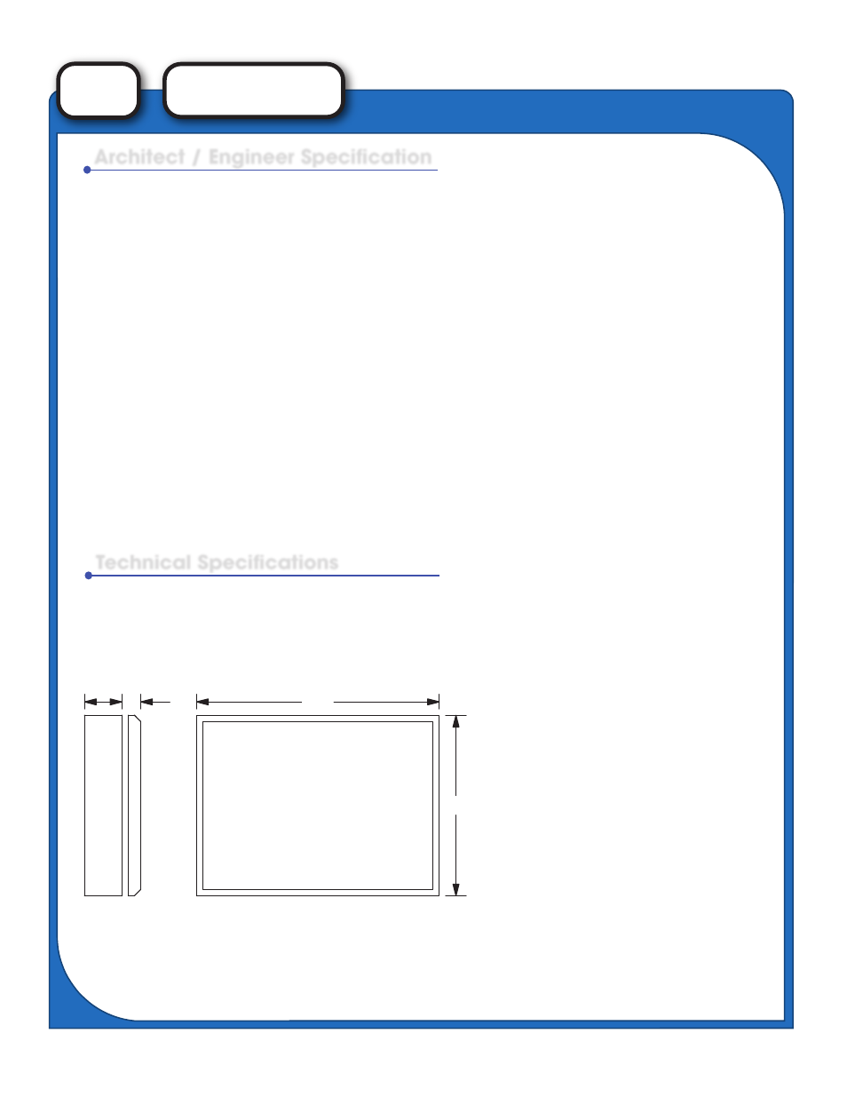
Additional Zones may be added to each enclosure size (such as the LW-4/4 shown on front).
Consult factory for details.
"W"
"H"
4"
7/8"
Backbox
Graphic Door
For Semi-flush mounting, add 3” to
overall “W” and “H” dimensions.
MODEL
LW-1
LW-4
LW-8
LW-12
ZONES
1
4
8
12
WIDTH x HEIGHT
18” x 9”
23 7/8” x 14”
23 7/8” x 24 1/2”
23 7/8” x 35”
NOTE: Units May Be Mounted
Vertical or Horizontal