Detection system zone leak, Wd-4 wd-1 – Light Engineered Displays WD-4 Control Panel User Manual
Page 2
The Contractor shall furnish, where indicated on the plans, a Water Leak Detection System. The standard features shall include
but not be limited to the following:
1. The system shall utilize linear water leak detection cable.
2. The system shall utilize limited power, low voltage A.C. for the detection circuits to protect the leak detection cable from
damage by electrolysis.
3. The system shall supervise the wiring and the water sensing conductors embedded in the leak detection cable. Any break
in the wiring shall cause a System Trouble indication at the leak detection control panel.
4. The system shall also include both Alarm and Trouble indications for each input zone as was as a common audible alarm
and auxiliary form-C contacts for connection to external monitoring systems.
5. System inputs shall have adjustable sensitivity to allow for proper operation over a broad range of ambient field conditions.
6. The control panel shall operate from 115 V.A.C. and shall include automatic battery backup using a 12v gel - cell battery.
The panel assembly is housed in a steel enclosure with hinged door and cam lock to prevent unauthorized access.
7. The system shall be Model WD-1 / -4 -8 -16 (specify) as manufactured by AquaALERT, a division of LED Incorporated.
WD
SERIES
DETECTION SYSTEM
ZONE LEAK
COM COM
- 12v
+5v +5v +12v
Sonalert
Z2
Z3
Z4
Programming Connector
Output to Status Board
Trouble
Future Serial Port
XPor t
RJ-45 output jack
Form "C" Contacts
System Inputs
connections
NC
NO
NO
COM
COM
NC
Alarm
120 VAC Input
12v Battery
Power Supply
+
-
-
+
12 vdc Battery Output
12 vdc Power Output
H N
CAUTION
System Enclosure
Z1
Power Supply
120 vac input
12 vdc output
H
N
12v Battery
+ -
Battery Input
Detection Zone
Terminate w/15kohm 1/4watt
System Contacts
Sensitivity Adj.
Enclosure
CAUTION
120 VAC
WD-4
WD-1
NOTES:
Nominal power is 115v AC - 60hz - 500ma. Route power away from all class-2 wiring. Power supply is a universal type
with an input voltage range of 85 -264v AC and 47 to 63hz. Output is approximately 13.5v DC, 2 amps max with
self-restoring overload protection.
Standby power is provided by a 12v 1.5 amp/hr gelled electrolyte battery. System Alarm and Trouble contacts are rated
for 1amp resistive load, max. (class 2) Relays shown de-energized. Each leak detection zone must be terminated with
a 15K ohm resistor.
10"
10"
WD-1
WD-4
Front View
Side View
Door
Backbox
4"
1"
Front View
WD-1
WD-4
WD-8
18"
9"
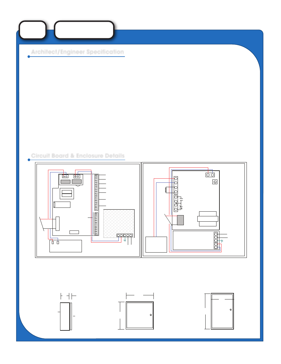
Architect/Engineer Specification
Circuit Board & Enclosure Details