Area of rescue assistance panel, Call station (1) call (8) station, Call for help – Light Engineered Displays ARA Panel w/no Intercom (ST) User Manual
Page 2
AREA OF RESCUE
ASSISTANCE PANEL
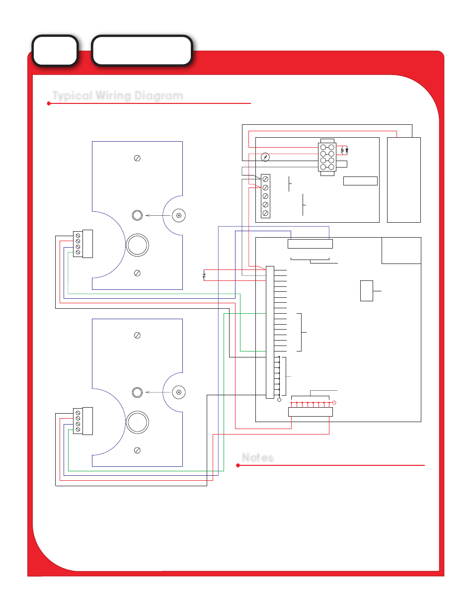
Typical Wiring Diagram
Notes
(-)
-
1. Power Input is to be fused. Fuse at 2 amps.
2. Install Ribbon Connectors with the stripe facing “up”.
3. Alarm Device must switch ______ to activate
indicators.
4. Standby current consumption is approximately 35
milliamps. Each indicator, when activated, adds 20
milliamps.
5. The numbered field inputs correlate to the enclosed
print.
CALL
STATION
(1)
CALL
(8)
STATION
LED (-) 2v
LED (+)
Sw. (Com.)
Sw. (N.O.)
4
3
2
1
PUSH
R
CALL FOR HELP
1. Push Button
2. LED Flashes
3. LED changes to steady
when call is received
LED (+)
4
3
2
1
LED (-) 2v
Sw. (Com.)
Sw. (N.O.)
PUSH
CALL FOR HELP
1. Push Button
2. LED Flashes
3. LED changes to steady
when call is received
R
Audible
Parallel with LED
Audible
Parallel with LED
RESET
SW
.
115VAC
115VAC TO 24VDC
S-25-12
PS-123X
(V) ADJ.
12VDC
12vdc Batter
y
(--)
(+)
100 Ohms 1Watt
1N4002 Diode
(Optional)
OUTPUTS 1k
FLASHING LEDS
12VDC RELAYS
FACTORY NOTES
INPUTS 1k
3022 CHIPS
GROUND
LINE
NEUTRAL
(-)V
(+)V
RIBBON
CONNECTOR
SOCKETS
SONALERT OUT.
LAMP TEST
ACK. SWITCH
OPTOCOUPLER COM.
BOARD #___
08
TB-2
01
02
03
04
05
06
07
08
1
OUT TO LED (+)
FROM
INPUTS
Sw. (N.O.)
01
02
03
04
05
06
07
1
Sw. (Com.)
OUTPUTS
TO
+ POWER IN
01
02
03
04
05
06
07
08
TB-3
08
07
06
05
04
03
02
01
OUTPUTS
TO
LED (-) 2v
01
02
03
04
05
06
07
08
09
10
11
12
13
14
15
16
17
18
19
20
21
22
23
24
TB-1
+ INDICATOR COM
+
+
+
+
-
-
-
-
-
-
-
-
+
-
ST
SERIES