Converter li-125 loop, General description & wiring, Dip switch designations – Light Engineered Displays LI Loop Converter Interface User Manual
Page 2
LI
SERIES
CONVERTER
LI-125 LOOP
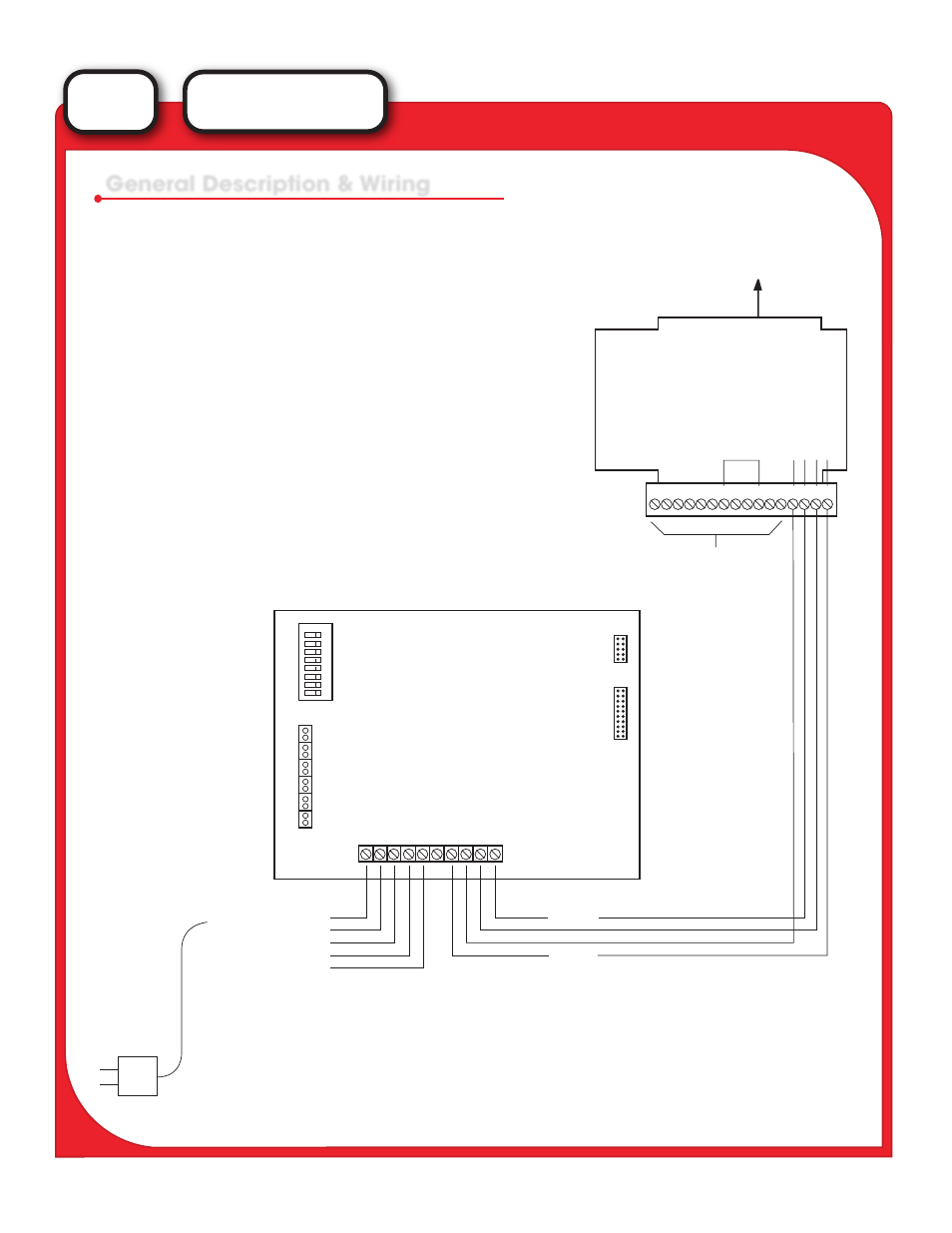
The LI-125 Interface may be located 1000’ from the XL-3 Control Panel. The printer and CRT plug into the
LI-125 using standard computer cables. The devices should be located within 50’ of the interface.
General Description & Wiring
1 2 3 4 5 6 7 8 9 10 11 12 13
Not Used
Transmit - Receive - Recieve + Transmit +
Slot 3 (J3)
MBX-1 in
First Enclosure
RS-232
Terminal
Printer Port
Centronics
*OUTPUT: Emulation: Wyse 50
Baud Rate: 9600
Parity: ODD
Data Bits: &/1
Full Duplex
Receive
+
-
Transmit
-
+
+
-
N.O.
N.C.
Comm
Relay*
12 VDC Pwr In
Plug-In Transformar
115 VAC to 12 VDC @ 500 ma.
*Relay can be used to activate local fault audible device.
Contacts are related at .5 amps at 115 VAC.
Circuit Board
DIP Switch Designations
1. This switch is “closed” to supervise for CRT.
“Open” switch to defeat supervision.
2. “Close” switch to supervise printer.
“Open” switch to defeat supervision.
3. “Close” switch to emulate RC-119
4. “Close” switch to activate answer-back.
If answer-back is provided by other device,
then switch must be “Open.”
5, 6, 7 Not Used.
8. Must be “Closed” when used with both a
printer / CRT combination, “Closed” for
printetr only, & “Open” for CRT only.
Dip SW
Program
Options
Monitor
LEDs
Disable CRT Alarm
Disable Printer Alarm
Answer Mode
Answer Enable
Current LP REC
Current LP XMIT
Sys Run
Printer Alarm
CRT Alarm
Power On
Not Used
1
2
3
4
5
6
7
8
1
2
3
4
5
6
7
8
9
10
11
12
14 15 16