Ordering information, Model, Width x height – Light Engineered Displays LCD-240G Graphic Map w/ Display User Manual
Page 2: Graphic map lcd-240 with
Consult the factory regarding custom sizes, products, options or special requirements.
A drawing is required showing the actual graphic representation needed for your project. The exact location of the indicator
points should be shown and identified by a legend. Mark the Annunciator location on the plans so that the artwork can be
oriented properly with a “You Are Here” designation.
Graphic sizes are shown below, according to model number. The maximum area available for artwork is the outside dimen-
sion, less two inches. We will work from your blueline, copy, fax, sketch, email or CAD file. Please note: a full size, inked
mylar, from your CAD drawing, will speed production.
Please complete the annunciator Order Form and send with drawing. If Order Form is not available, indicate how annuncia-
tor will be activated and list any specifications required.
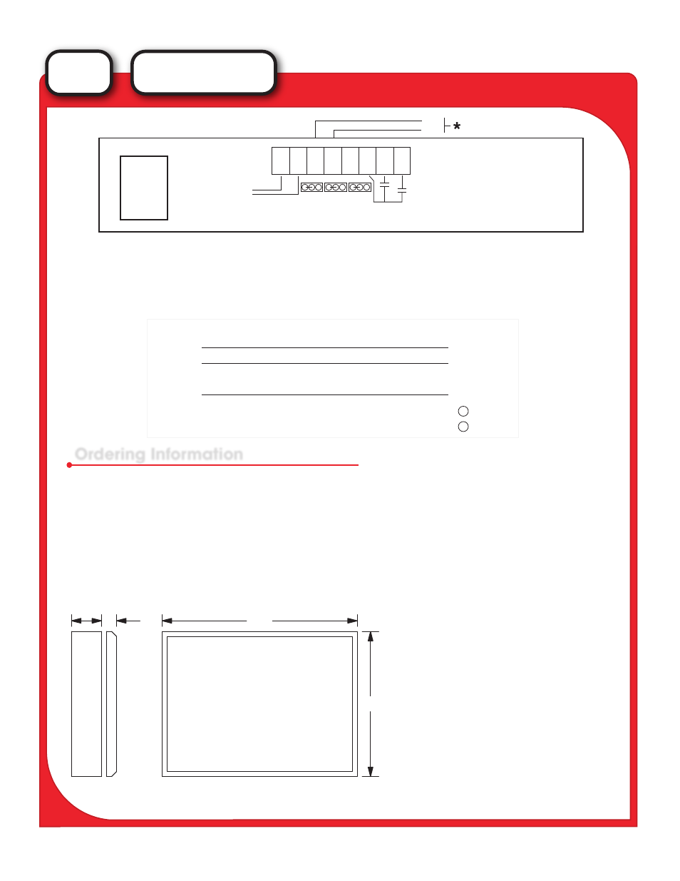
1. For RS-232 operation, Jumper pins 1 & 2 on J1, J2 and J3 (shown for RS-232).
2. For RS-485 operation, Jumper pins 2 & 3 on J1, J2 and J3.
* RS-485 Input: Connect TXA to TB-1, Terminal 4.
Connect TXB to TB-1, Terminal 3.
3. For RS-485 operation, the CCM must be connected to a data converter. The converter OUTPUT is connected
to the individual LCD-240 unit(s). Consult LED for assistance.
Ordering Information
"W"
"H"
4"
7/8"
Backbox
Graphic Door
For Semi-flush mounting, add 3” to
overall “W” and “H” dimensions.
MODEL
LCD-240/1G
LCD-240/2G
WIDTH x HEIGHT
23 7/8” x 14”
23 7/8” x 24 1/2”
NOTE: Units May Be Mounted
Vertical or Horizontal
LCD
SERIES
GRAPHIC MAP
LCD-240 with
TX 1.
SG 2.
RTS 3.
CTS 4.
NC 5.
RX 6.
R (3)
S (5)
X (4)
+
-
Inter-Connections
LCD-240
CCM
Power Input
8 to 12 volts
2
1
12 vdc
-
+
TB-1
TB-8
Connect Momentary Switches
for Scroll UP/DOWN Function
LCD-240 REAR VIEW
- + R X S C D U
12/24 VDC Input
1
2
3
4
5
6
7
8
TXB
TXA
J-1
1 2 3 1 2 3 1 2 3
J-2
J-3