Light Engineered Displays FS Series PURGE PANEL CONTROLLER User Manual
Page 2
FS
SERIES
CONTROLLER
PURGE PANEL
Switches S1 - S4 are used to set the initial count down time of the TA-123PP. Each is set to the digit of the initial
count in the format of MM:SS where MM is the minutes to count and SS is the seconds to count. You may set
the minutes to count on S1 and S2 (S1 is 10 min and S2 is 1 min) from 0 to 99 minutes. S3 and S4 set the
seconds to count from 0 to 59 seconds. If S1 and S2 are set to 00 minutes, then S3 and S4 may be set from 0
to 99 seconds.
Setting the Purge Delay
Purge timer is activated by the suppression system discharge contacts. After the preset user-adjustable time
delay has expired, the Purge Key Switch is enabled. Operate Key Switch to energize the Purge Fan start relay.
Remote relay contacts close to start the Purge Fan.
Specifications: 24 vdc input filtered and regulated 155ma standby, 175ma activated and 335ma purge
engaged.
Additional Information
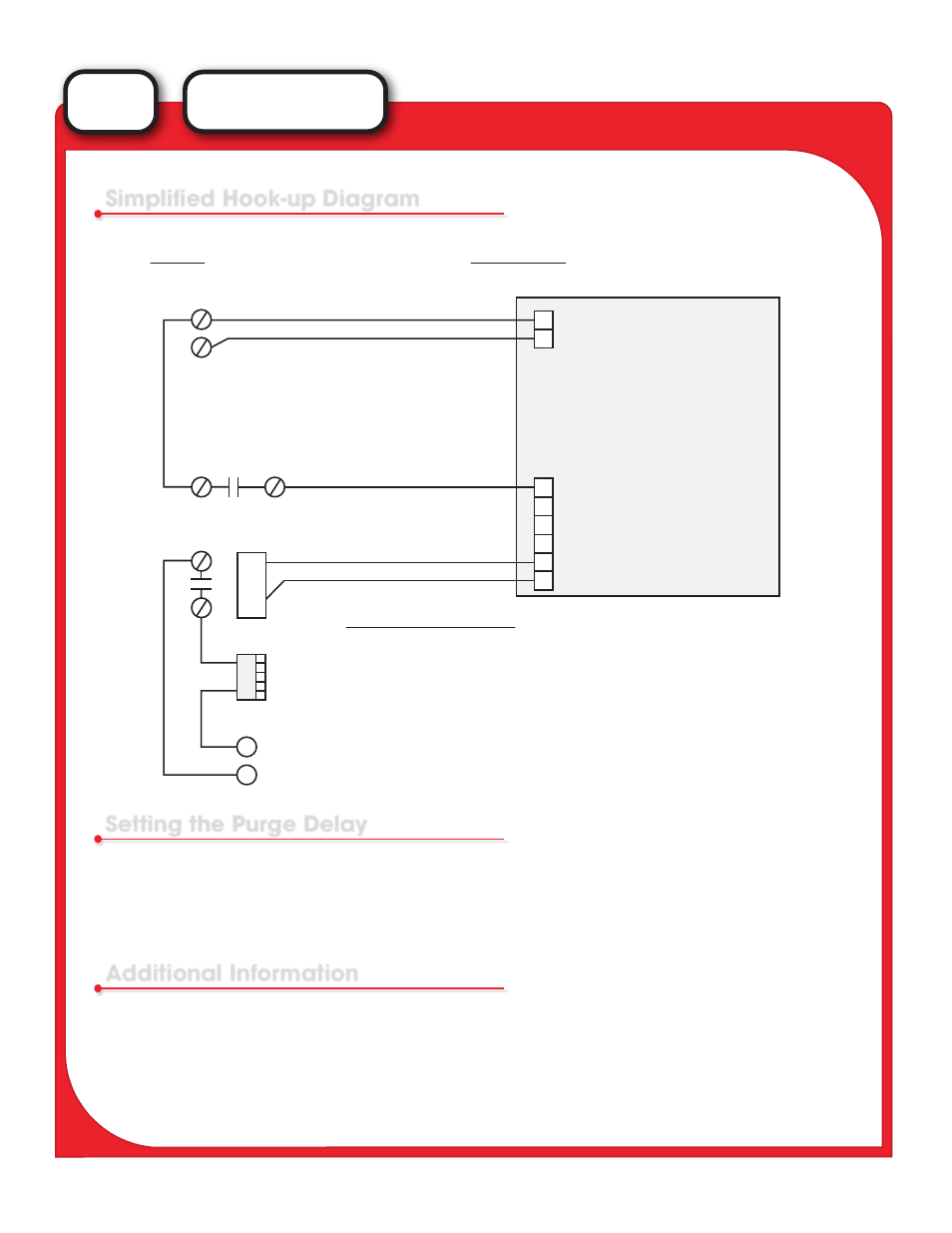
Simplified Hook-up Diagram
FACP
TA-123PP
24 vdc power
Discharge Contact in FACP
Relay - Mounted at Purge Fan
Purge Fan
120 VAC - Typical for Purge Fan
Power Input - 24 VDC
Trigger -
Starts Timer Sequence
24 VDC Output
for remote relay
+
+
-
+
-
R
1
N
H